Pre Meshing
Perform Pre Meshing operations on the imported model.
You will perform the pre meshing tasks for the imported model before proceeding to meshing and deck setup operations.
- Hole/Gap Fill of discontinuous horizons.
- Refine mesh to achieve better mesh quality.
- Verify Horizon intersections.
- Split Faults
Hole & Gap Fill
Fill a gap in the Horizon-C and Horizon-F components.
-
Click Mesh icon, select .
 Figure 1. Hole/Gap Fill dialog will appear.
Rebuild Mesh
Use Rebuild option to rebuild the mesh of components.
Note: In order to perform Rebuild, you will have to import the
mesh parameter and mesh criteria files to the session. The sample parameter and
criteria files,
geod_500.param and
geod_500.criteria are present in the Tutorial
folder.-
From gMesh group, select .
 Figure 2. A guide bar will appear.
 -
Click
 to open additional options.
 Figure 3.
 -
Click Edit parameters. A dialog will appear.
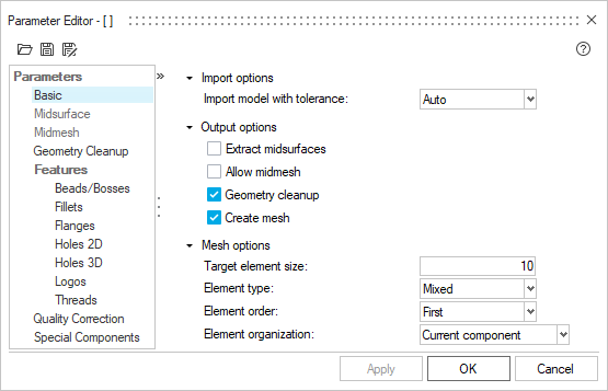 Figure 4.
 -
Click
 .
A file browser will appear. Browse and select the
.
A file browser will appear. Browse and select thegeod_500.paramfile.This will update the mesh parameter for the session from selected file.
Mesh Rebuild Definition:
For the tutorial purpose, you will rebuild
mesh for the following components-
- Fault A
- Fault B
- Fault C
- Horizon Top
- Horizon A
- Horizon B
- Horizon C and
- Horizon F
-
Select the advanced options button (
 ) next to Elements button.
Horizon Intersection
Use Horizon tool to check and fix horizon intersections.
Auto Method
-
From Fix group, select the Horizon tool.
 Figure 5. A guide bar will appear.
 -
Click to open additional options.
Manual Method
Isolate Horizon-C and Horizon-D components.
-
From Fix group, select the Horizon tool. Deactivate
 to enable the manual method.
-
Click Push: Pinchout
 .
This pushes the intersecting elements away from each other, with the older horizon being forced below the younger one. The minimum unit thickness now corresponds to the value specified.
.
This pushes the intersecting elements away from each other, with the older horizon being forced below the younger one. The minimum unit thickness now corresponds to the value specified. -
Click Next
 to find the next intersection.
-
Click Intersect and Remesh
 for the larger intersection patch. Click
Delete in the microdialog.
This cuts and stitches the intersecting horizons and deletes the duplicate elements.
for the larger intersection patch. Click
Delete in the microdialog.
This cuts and stitches the intersecting horizons and deletes the duplicate elements.
Intersect Faults
Intersect and split faults using the horizons.
-
From Fix group, select the Faults tool.
 Figure 6. A guide bar will appear.
 -
Click
 .
This will intersect all the faults and horizons. This also splits the faults and organizes them into sub components delineated by the stratigraphy.
.
This will intersect all the faults and horizons. This also splits the faults and organizes them into sub components delineated by the stratigraphy.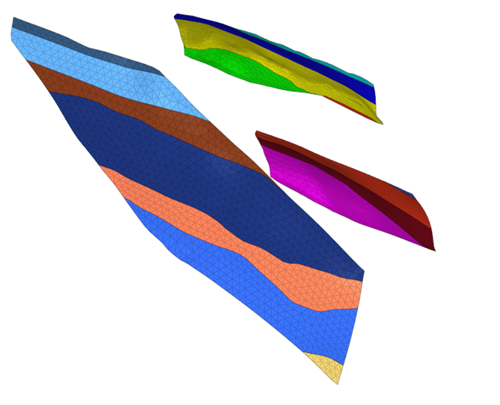 Figure 7.
Enclose
Use Enclose option to create walls for all the horizon component pairs.
-
From the Define group, select Enclose.
 Figure 8. A guide bar will appear.
 -
Deactivate
 to enable manual mode. Select
By Horizons from the list.
to enable manual mode. Select
By Horizons from the list.
-
Click to open additional options.
Enter
500for Element Size. -
Similarly, create sidewalls between each pair of horizons by choosing them
in a top-down (numerically lowest to highest; that is, youngest to oldest)
order.
Once complete, the model with sidewalls should be as below.
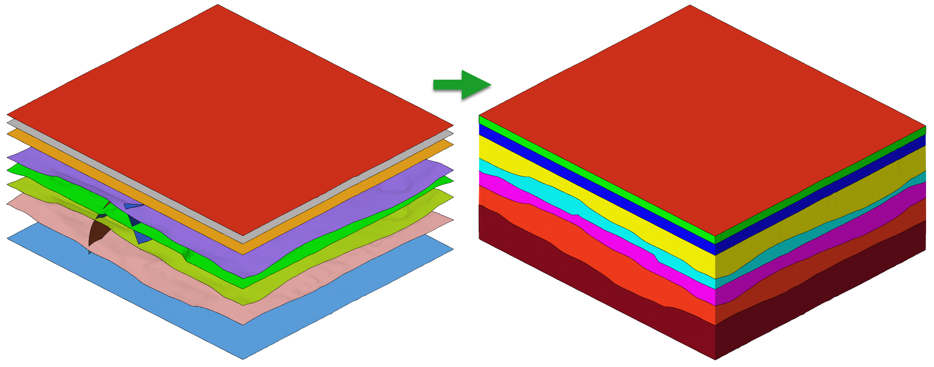 Figure 9.
Auto Organize Components and Elements
Organize model components and fault elements into unique collectors.
Organize Volumes
-
From Define group, select Organize
tool.
 Figure 10. A guide bar will appear.
Organize Volumes
-
Click
 .
The Assemble Enclosed Volumes dialog is displayed. Click OK to accept the organization and close the dialog.
.
The Assemble Enclosed Volumes dialog is displayed. Click OK to accept the organization and close the dialog. Figure 11. This creates volume assemblies based on the horizon pair and the respective sidewalls. These volumes will now be used for volume tetra meshing.
 Figure 12.