Kinematic Draping Theory
Layered composite structures are typically formed by placing reinforced plies against a mold surface in desired orientations.
In the case of flat and singly curved surfaces, the orientation of the ply stays practically unchanged over the whole application area. When it comes to doubly curved surfaces, a ply can follow the surface only by deforming. In particular, dry and pre-impregnated woven fabrics can adapt to the shape of a doubly curved surface without use of excessive force. Deformation occurs with in-plane shear and up to certain deformation level, the shear stiffness of the fabric is insignificantly small. [1]
When a ply deforms by shearing to follow the surface, the fiber orientation changes. Different approaches have been developed for the simulation of the so-called draping process. [2] The need for draping simulation is twofold. Firstly, the manufacturability of the composite product can be assessed. Areas where the reinforcement cannot follow the surface are indicated and hence measures can be taken in design to avoid this. Secondly, the draping simulation gives the actual fiber orientations at any location in the model. This information is needed for accurate finite element analysis of the structure.
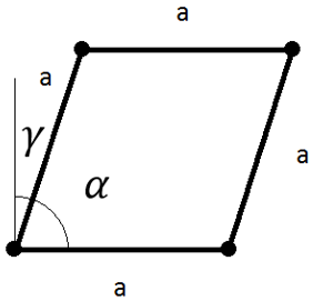
Figure 1.
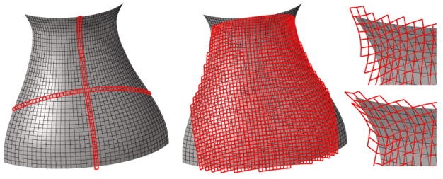
Figure 2.
Draping of the elements that have two known node points (left). Draping propagation is on initially orthogonal directions. Draping of the elements that have three known node points (middle). The coverage is based on the primary draping paths. Restart of the draping (right) and full coverage. For the restart, the default Relaxation angle has been first used. Then, the maximum Relaxation angle is used. The associated model Revolution.hm can be found in the tutorials\hm folder of your installation.
From this, the locations of the two node points can be determined with an iterative minimization algorithm.
The draping simulation starts from a given seed point and progresses in the given draping direction. In this phase each draping element has initially two known node points. Draping elements are laid until the model edge is reached. The procedure progresses simultaneously in all four primary directions (by default this is set to on), which are initially orthogonal. Parallel to the draping of primaries, the draping elements with three known nodes are populated. The algorithm resolves if the whole model is draped or if there are areas where the draping simulation needs to be restarted.
Restart is initiated from the middle of the draping patch edge. At the location of the restart, two nodes are known and the two unknowns need to be determined with the energy minimization. Without constraining, the solution typically yields a very relaxed draping mesh. User can control the recovery of the draping mesh with the relaxation angle parameter (default 3 degrees). This parameter limits the level of relaxation with respect to its parent draping element. Then, the algorithm sweeps the row of draping elements on the edge of concern, proceeds to other undraped edges and so on.
The simulation determines fiber principal directions 1 (warp) and 2 (weft). Draped fiber directions 1 are mapped to the finite element model to correct material orientations accordingly. Woven ply can be split to two unidirectional plies with ply orientations 0 and 90, respectively, and draped separately.
It expresses the deviation from the ideal non-sheared case. The visualization of beta values over the model surface is useful for depicting problem areas. Shear values are mapped to the FE mesh and are available as absolute values. For most fabric reinforcements, the maximum deformation angle alpha is 30-40 degrees. [6] When a fabric is sheared to a specific deformation level, the shear force starts to increase radically with only little increase in the shear deformation. This limit is called the locking angle. Beyond this limit buckling can be observed. In the Kinematic Draping dialog, the default value for β is set to 55 degrees. The locking angle of a reinforcement can be determined experimentally. [7]
The pin joint net model is specifically developed for woven fabrics, but it has been proven to work for cross ply prepreg stacks and for single unidirectional plies when the deformation is moderate. [8]
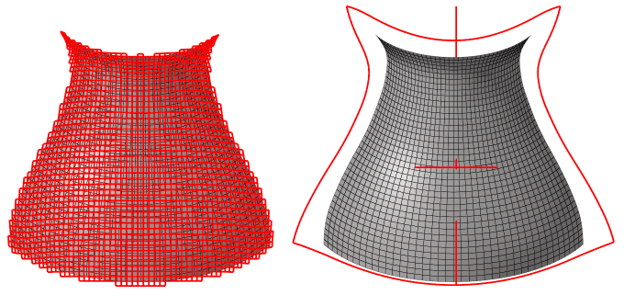
Figure 3.
References
Deep drawing of fabric reinforced thermoplastics, Bergsma OK, Huisman J., In: Brebbia CA, de Wilde WP, Blain WR, editors. Computer aided design in composite material technology, New York: Springer, 1988. p. 323-334.
Algorithms for draping fabrics on doubly-curved surfaces, Van der Ween F., Int J Numer Meth Eng 1991;31:1415-1426.
The influence of accurate stretch data for reinforcements on the production of complex structural moldings. Part 1. Deformation of aligned sheets and fabrics, Potter KD., Composites 1979;10: 161-167.
The draping of woven fabric preforms and prepregs for production of polymer composite components, Wang J et al. Composites: Part A 30 (1999) 757-765.
Fabric draping simulation in composites manufacturing Part II. Analytical methods, Van West BP, Luby SC., J Adv Mater 1997;28(3):36-41.
Experimental studies and analysis of the draping of woven fabrics, Mohammed U et al. Composites: Part A 31 (2000) 1409-1420.
On the relationship between shear angle and wrinkling of textile composite preforms, Prodromou AG, Chen J. Composites: Part A 28A (1997) 491-503.
Bias extension measurements on cross-plied unidirectional prepreg, Potter K. Composites: Part A 33 (2002) 63-73.
Fitting a woven-cloth model to a curved surface: mapping algorithms, Aono M., Breen D.E. and Wozny M.J., Computer-Aided Design, Volume 26, Issue 4, April 1994, 278-292.
A Geometry Information Based Fishnet Algorithm for Woven Fabric Draping in Liquid Composite Molding, Yang B, Jin T., Bi F. and Li J., ISSN 1392–1320 Materials Science (MEDŽIAGOTYRA). Vol. 20, No. 4. 2014.