Part Replacement
Use the Part Replacement tool replace one or more parts with an existing part in your model or a part from an external file.
Single Part Replacement
-
In the Tolerance field, enter a tolerance to search for
closest nodes and elements to re-establish the connections and other references
between the target part and the model.
The default tolerance is set at 0.01.
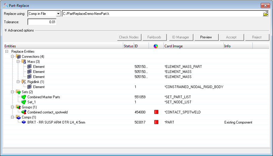
Figure 1. -
Click Preview to show the status of the reconnection of
the target part to the model.
Tip: If you change the tolerance, you can click Preview to re-examine the effect of the change before accepting it.
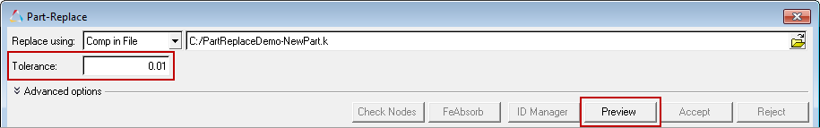
Figure 2. -
To display connections, click Check Nodes.
Connections are displayed in the Status column and in the graphics area.
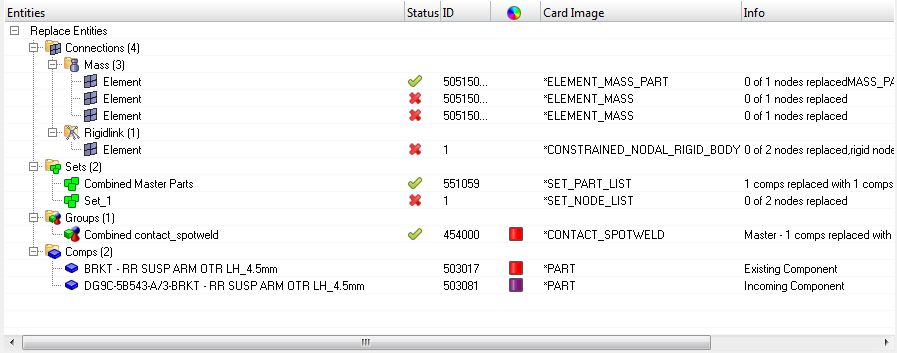
Figure 3.In the graphics area, green connections are highlighted white and red connections are highlighted red.
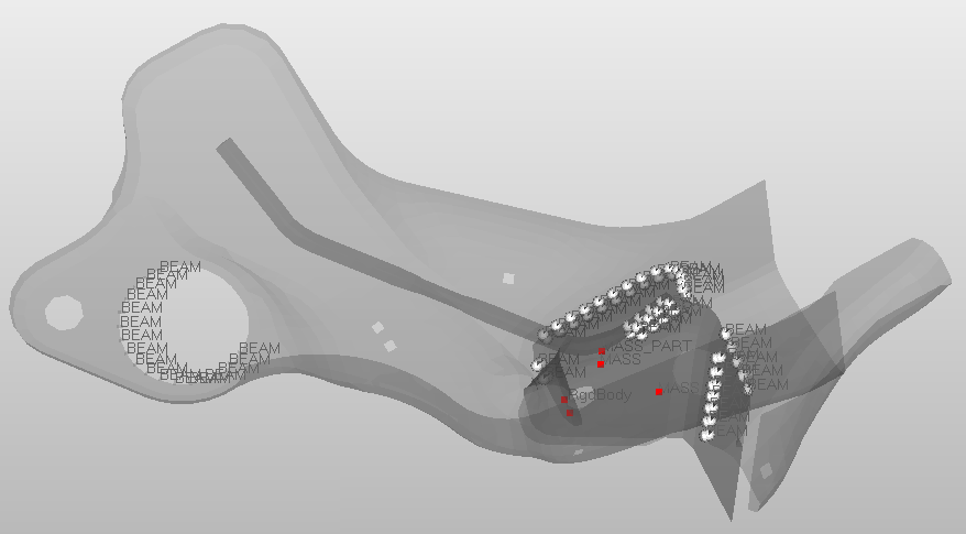
Figure 4. -
Adjust the tolerance for the target part as needed, then click
Preview to see the status.
In the example below, the tolerance is changed to 5 and all of the connections are re-established.
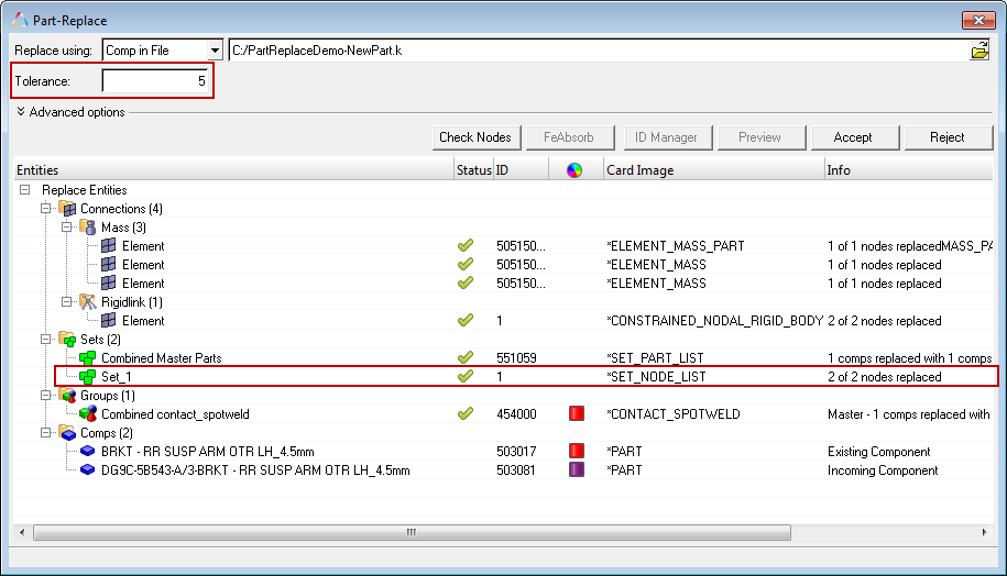
Figure 5.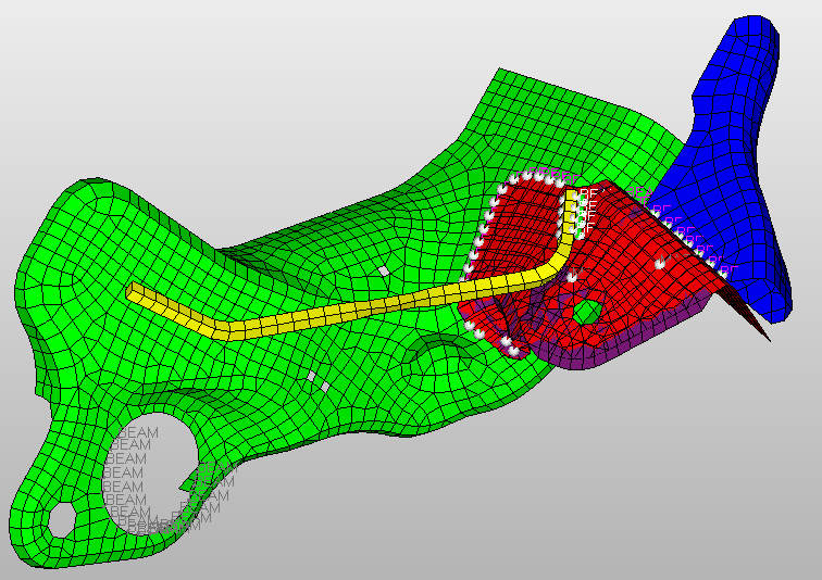
Figure 6.
Multicomponent Replacement
Multiple components and their corresponding entities can be replaced simultaneously using the Part Replacement tool.
Multicomponent replacement enables you to quickly replace components with a different mesh, replace components with a change in design, or replace components with a different design and internal connections.
After part replacement has completed, if both the source and target have the same name, the Assembly structure and Component names will be retained.
-
From the Model Browser, right-click on the components or
Include file that contains the components to replace and select or Automatic from the context menu.
Note: When replacing more than one component at a time, all selected components should be organized in one Include file.
- Choose Manual to automatically pair components. You can manually change the component pair and decide which entities to retain post replacement.
- Choose Automatic to automatically pair components based on the bounding box or collision detection approach. You have no control over component pairing.
The Part-Replace dialog opens and lists all possible entities affected by the part replacement.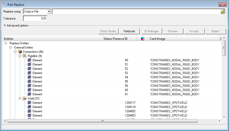
Figure 7. - Optional:
To preserve internal entities so that they will not be deleted after part
replacement, in the Preserve column, enable the checkbox.
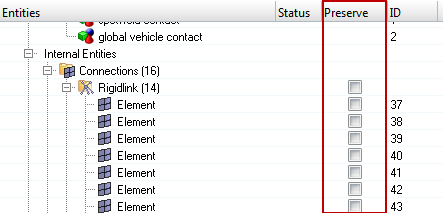
Figure 8. -
If you are manually replacing components in the Component
Pairing dialog, modify the component pairing and click
OK.
- In the Incoming field, select whether to remove the pairing, add a new pairing, select a new pairing, or select to not replace the references.
- Review, show (show all), isolate, or reset the components in the pair using the options in the right-click context menu.
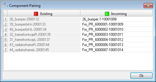
Figure 9. -
In the Entities Selection dialog, specify replacement
methods for incoming/existing entities and click OK.
- Choose Accept incoming entities (existing entities deleted) to delete all of the internal entities on accept.
- Choose Accept existing entities (Incoming entities deleted) to delete all of the incoming entities on accept.
- Choose Merge existing and incoming entities (no entities deleted) to retain both existing and incoming entities on accept.
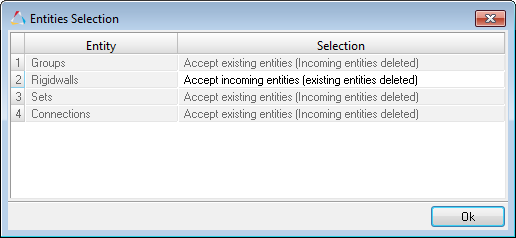
Figure 10. -
Check the status of each entity.
Note: All internal entities are deleted, and all external entities are updated.
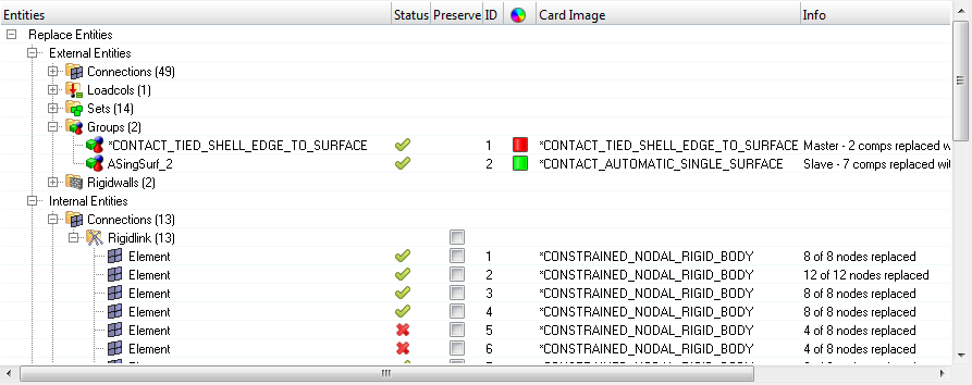
Figure 11.