Front Multi-link
The multi-link suspension derives its name from the fact that it is made up of three or more links. The MotionView multi-link suspension contains four links, and it is generally used on cars and off-road vehicles. This suspension offers flexibility to the designer, since each link’s location can be determined independently.
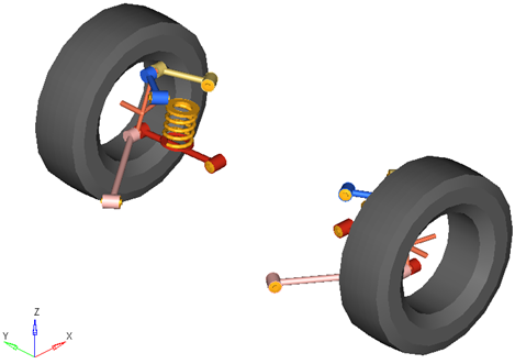
Figure 1. Front Multi-link Suspension
Model Use
- The wheel body represents the mass and inertia of the tire and the rim.
- The wheel hub body represents the mass and inertia of other rotating bodies such as a brake rotor, but not the half-shafts if the suspension is driven. The wheel hub and brake rotor have no associated graphics.
- The wheel and wheel hub parts use the Wheel CG location as the center of gravity.
- Each body’s Center of Gravity (CG) is estimated from the body’s geometry. The formulas are coded into the point panel and can be seen via the graphical user interface. If more accurate CG locations are available they should be used.
- The point giving the location of the ball joint between the suspension knuckle and steering tie rod point resides in the steering system.
- A wide variety of combinations of suspensions and subsystems can be built using the
Assembly Wizard. You are encouraged to build systems and
understand the resulting model using the graphical user interface.
When building a new suspension model, build the model with all of the optional systems (stabilizer bar, etc) included in the model. Immediately turn off the systems using the Project Browser and run an analysis on the base suspension to ensure it solves properly. As data becomes available for the optional systems; activate those systems and populate them with data.
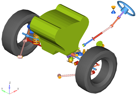
Figure 2. Front-Half-Vehicle Model Employing a Multi-link Suspension
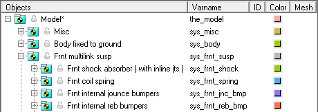
Figure 3. Browser View of a Front-Half-Vehicle Model Systems and Subsystems Employing a Multi-link Suspension
Points
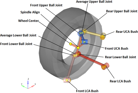
Figure 4. Right Side Principal Points – Front Multi-link Suspension
Bodies
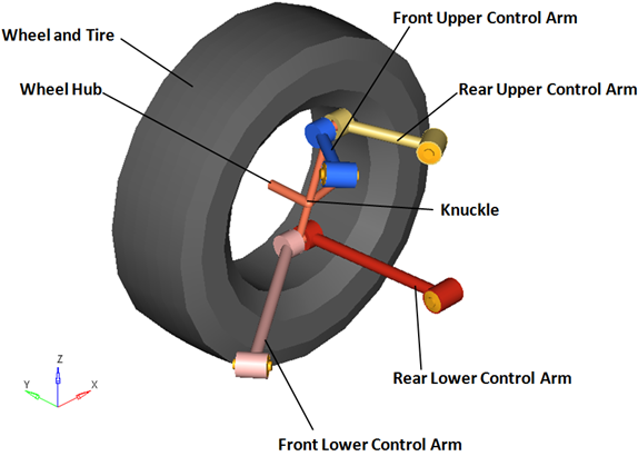
Figure 5. Right Side Bodies – Front Multi-link Suspension
Bushings and Joints
| Label | Type | Body 1 | Body 2 | Point | Notes |
|---|---|---|---|---|---|
| Front Lower Ball Joint | Spherical | Knuckle | Front Lower Control Arm | Front Lower Ball Joint | When the Compliant option is set to No, the compliance for this joint is turned "Off" and behaves as a pure spherical joint. |
| Rear Lower Ball Joint | Spherical | Knuckle | Rear Lower Control Arm | Rear Lower Ball Joint | When the Compliant option is set to No, the compliance for this joint is turned "Off" and behaves as a pure spherical joint. |
| Front Upper Ball Joint | Spherical | Knuckle | Front Upper Control Arm | Front Upper Ball Joint | When the Compliant option is set to No, the compliance for this joint is turned "Off" and behaves as a pure spherical joint. |
| Rear Upper Ball Joint | Spherical | Knuckle | Rear Upper Control Arm | Rear Upper Ball Joint | When the Compliant option is set to No, the compliance for this joint is turned "Off" and behaves as a pure spherical joint. |
| Wheel Spindle | Revolute | Wheel Hub | Knuckle | Wheel Center | |
| Wheel Hub Fix Jt |
Fixed Joint | Wheel | Wheel Hub | Wheel Center | When the Spindle compliance option is set to Yes, the joint type changes to universal. |
| LCA Front Bush | Universal | Front Lower Control Arm | Subframe, Vehicle Body or Ground | Front Lower Control Arm Bush | When the Compliant option is set to No, this joint compliance is turned "Off" and behaves as a pure universal joint. |
| LCA Rear Bush | Universal | Rear Lower Control Arm | Subframe, Vehicle Body or Ground | Rear Lower Control Arm Bush | When the Compliant option is set to No, this joint compliance is turned "Off" and behaves as a pure universal joint. |
| UCA Front Bush | Universal | Front Upper Control Arm | Subframe, Vehicle Body or Ground | Front Upper Control Arm Bush | When the Compliant option is set to No, this joint compliance is turned "Off" and behaves as a pure universal joint. |
| UCA Rear Bush | Universal | Rear Upper Control Arm | Subframe, Vehicle Body or Ground | Rear Upper Control Arm Bush | When the Compliant option is set to No, this joint compliance is turned "Off" and behaves as a pure universal joint. |
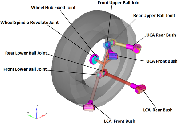
Figure 6. Right Side Joints and Bushings - Front MacPherson Strut Suspension with Two (2) Piece Lower Control Arm
Similar Suspensions
front MacPherson strut (1pc LCA)
front MacPherson strut (2pc LCA)
Rear SLA (1pc LCA)
Rear SLA (2pc LCA)