Front Internal Jounce Bumper
The internal jounce bumper system is used to simulate a jounce bumper that is internal to the shock absorber, or strut, on a front or rear suspension. The system creates forces, requests, and graphics of the bumper. The force acts between the strut or shock rod and the strut or shock tube. The bumper is oriented using lengths along the strut/shock instead of XYZ coordinates. The force-deflection characteristics of the jounce bumper are defined by the curve in the jounce bumper system. In models built via the Assembly Wizard, the jounce bumper system is a child of the suspension system.
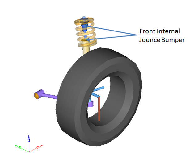
Figure 1. Front Internal Jounce Bumpers with Full Vehicle
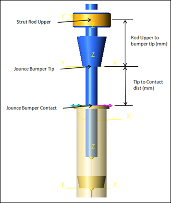
Figure 2. Jounce Bumper Points and Distances
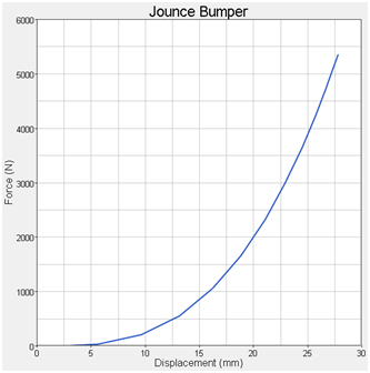
Figure 3. Jounce Bumper Force - Deflection Curve
Figure 4.
- The force element in the system uses an expression to turn on and off the jounce bumper when the tip reaches the contact.
- Linear extrapolate is on by default in the jounce bumper curve. For robust simulations, make sure the force deflection curve values exceed the forces and deflections seen in the simulation.
- The system uses calculated point locations to define the graphics and force locations. Markers (based on the points) are used in the force expression.
- The force deflection curve of the jounce bumper is 0,0 when the bumper just touches the contact point, and is a positive pair of points after contact.
- The graphics are defined so the jounce bumper graphic (represented by the cone) begins to pass through the contact plane graphic (a flat round plate) at the same time the jounce bumper force initiates.
- The jounce bumper force acts at the “contact point” and is an action/reaction force which acts along the axis of the strut, or shock, between the strut/shock rod and the strut/shock tube bodies.
- Damping is ignored, however it is able to be added.
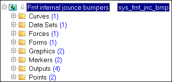
Figure 5. Project Browser View - Front Internal Jounce Bumper
Curves
A single curve is included in the system (Jounce Bumper 1). The curve defines the force-displacement behavior of the jounce bumper. The 0,0 point on the curve is when the bumper initially contacts the contact surface. Data should always be in the positive quadrant and should always increase in both the X and Y directions.
Data Sets
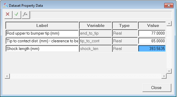
Figure 6. Dataset Property Dialog - Datasets - Jounce Bumper Lengths
- Rod upper to bumper tip (mm)
- Determines the coordinates of the jounce bumper tip PointPair.
- Tip to contact dist. (mm) - clearance to be set manually in the curve x offset
- Determines the coordinates of the jounce bumper contact PointPair.
- Shock length (mm)
- Parametric value that determines the PointPair co-ordinates for “jounce bumper tip”
and “jounce bumper contact”.
It is of the form:
sqrt((p_rod.l.x-p_tube.l.x)^2+(p_rod.l.y-p_tube.l.y)^2+(p_rod.l.z-p_tube.l.z)^2)
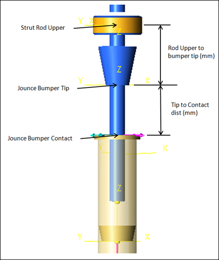
Figure 7. Datasets - Jounce Bumpers Lengths
Forces
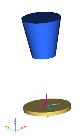
Figure 8. Principal Forces - Front Internal Jounce Bumper
Forms

Figure 9. Forms - Jounce Bumpers Lengths
Graphics
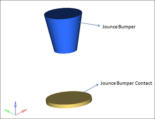
Figure 10. Jounce Bumper and Jounce Bumper Contact Graphics
Markers
Two markers that are symmetrical about XZ plane are used in the front internal jounce bumper system (force direction reference and displacement reference).
| Marker | Location Description | Use |
|---|---|---|
| Force Direction Reference | Origin is at the strut rod upper or shock upper bush. Z axis points at the Jounce bumper contact Attached to the Strut tube (lwr strut) or shock tube (lwr shk). |
The jounce bumper force acts along the z axis of this
marker. The jounce bumper force request reports forces in this reference frame. |
| Displacement Reference | Origin is at the jounce bumper tip. Z axis points at the Strut rod upr or shock upper bush. Attached to the Strut rod (upr strut) or shock rod (upr shk). |
The jounce bumper displacement request is measured in
this coordinate frame. The jounce bumper force expression uses this marker in the equation to calculate force. |
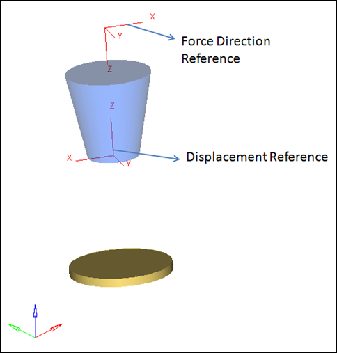
Figure 11. Markers - Front Internal Jounce Bumper
Outputs
- Left Jounce Bumper Displacement
- Displacement of the jounce bumper on the left side of the vehicle. Displacement of the bumper contact relative to the bumper tip, and the displacement of the contact tip relative to the bumper contact are reported. Both requests are in the displacement marker reference frame.
- Right Jounce Bumper Displacement
- Displacement of the jounce bumper on the right side of the suspension. The contact tip relative to the bumper contact are reported. Both requests are in the displacement marker reference frame.
- Left Jounce Bumper Force
- The jounce bumper force on the left side suspension. The force pushes the bodies apart when the bumper is engaged. The force is reported on both parts of the force element, and the forces will be equal and opposite.
- Right Jounce Bumper Force
- The jounce bumper force on the right side of the suspension. The force pushes the bodies apart when the bumper is engaged. The force is reported on both parts of the force element, and the forces will be equal and opposite.
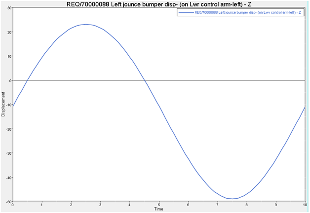
Figure 12.
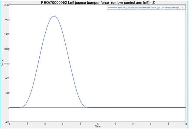
Figure 13.
Points

Figure 14. Jounce Bumper Points and Dimensions
- Coordinate
- Expression (Front-Left)
- X
- p_rod.l.x+(p_tube.l.x-p_rod.l.x)/ds_jnc_bmp.shock_len.value*ds_jnc_bmp.end_to_tip.value
- Y
- p_rod.l.y+(p_tube.l.y-p_rod.l.y)/ds_jnc_bmp.shock_len.value*ds_jnc_bmp.end_to_tip.value
- Z
- p_rod.l.z+(p_tube.l.z-p_rod.l.z)/ds_jnc_bmp.shock_len.value*ds_jnc_bmp.end_to_tip.value
- Expression
- Model Equivalent
- p_rod.l.x
- X coordinate of the Upper Rod Attachment Point – Left
- p_tube.l.x
- X coordinate of the Lower Tube Attachment Point – Left
- p_rod.l.y
- Y coordinate of the Upper Rod Attachment Point – Left
- p_tube.l.y
- Y coordinate of the Lower Tube Attachment Point – Left
- p_rod.l.z
- Z coordinate of the Upper Rod Attachment Point – Left
- p_tube.l.z
- Z coordinate of the Lower Tube Attachment Point – Left
- ds_jnc_bmp.shock_len.value
- Total shock length value defined in the dataset
- ds_jnc_bmp.end_to_tip.value
- Distance from the shock rod upper to bumper tip defined in the dataset
- Coordinate
- Expression (Front-Left)
- X
- p_rod.l.x+(p_tube.l.x-p_rod.l.x)/ds_jnc_bmp.shock_len.value*(ds_jnc_bmp.end_to_tip.value+ds_jnc_bmp.tip_to_cont.value)
- Y
- p_rod.l.y+(p_tube.l.y-p_rod.l.y)/ds_jnc_bmp.shock_len.value*(ds_jnc_bmp.end_to_tip.value+ds_jnc_bmp.tip_to_cont.value)
- Z
- p_rod.l.z+(p_tube.l.z-p_rod.l.z)/ds_jnc_bmp.shock_len.value*(ds_jnc_bmp.end_to_tip.value+ds_jnc_bmp.tip_to_cont.value)
- Expression
- Model Equivalent
- p_rod.l.x
- X coordinate of the Upper Rod Attachment Point – Left
- p_tube.l.x
- X coordinate of the Lower Tube Attachment Point – Left
- p_rod.l.y
- Y coordinate of the Upper Rod Attachment Point – Left
- p_tube.l.y
- Y coordinate of the Lower Tube Attachment Point – Left
- p_rod.l.z
- Z coordinate of the Upper Rod Attachment Point – Left
- p_tube.l.z
- Z coordinate of the Lower Tube Attachment Point – Left
- ds_jnc_bmp.shock_len.value
- Total shock length value defined in the dataset
- ds_jnc_bmp.end_to_tip.value
- Distance from the shock rod upper to bumper tip defined in the dataset
- ds_jnc_bmp.tip_to_cont.value
- Distance from the bumper tip to bumper contact defined in the dataset
Similar Suspensions
Rear Internal Jounce Bumpers
Front Internal Rebound Bumpers
Rear Internal Rebound Bumpers