Triangles as Thin Anisotropic Dielectric Sheet
This option defines a thin anisotropic dielectric sheet. The definition is similar to the isotropic dielectric sheet, except that the layers are anisotropic.
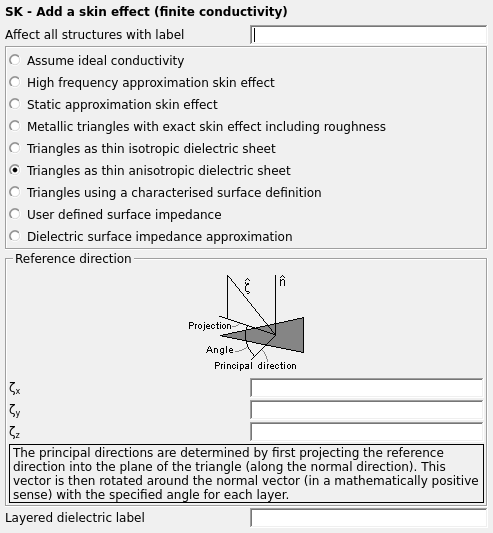
Figure 1. The SK - Add a skin effect (finite conductivity) dialog.
Note: The material parameters for the anisotropic dielectric sheet are defined with the DI and
DL cards. The SK card then uses the label defined at the DL card.
The principal direction in each layer is defined by the angle
(see Angle in the dialog image)
relative to the projection of the vector
(Reference direction group) onto the
plane of the triangle (in the DI card). Here
is measured in the mathematically positive sense with respect
to the normal vector of the triangle.
Tip: POSTFEKO can
be used to display the fibre direction and to check visually that the input file is
correct.
In this case the card line is followed by an additional line for each
layer. The medium properties in the principle direction is different from those in
the orthogonal direction which lies in the plane of the triangle and orthogonal to
the principal direction.Parameters:
- Reference direction
- The X, Y and Z components of the vector (used to define the principal direction, see image on the dialog).
- Layered dielectric label
- Label of the layered dielectric medium which will be used (as specified in the DL card).