CI Card
The CI card is used to define interconnections and terminations between cables.
In the Solve/Run tab, in the Cables group,
click the ![]() Interconnect cable
(CI) icon.
Interconnect cable
(CI) icon.
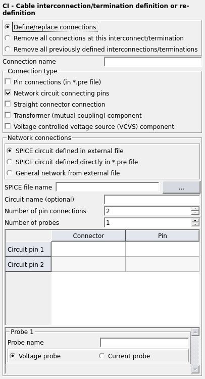
Figure 1. The CI - Cable interconnection/termination definition or re-definition dialog.
Parameters:
- Define/ replace connections
- New connection, replaces previous connections with the same name.
- Remove all connections at this interconnect/termination
- All previously defined connections (with this name) at this specific interconnection/termination are removed.
- Remove all previously defined interconnections/terminations
- All previously defined interconnections/terminations are removed.
- Connection name
- The name of the connection.
- Pin connections (in .pre file)
- The connection between pins are specified in the .pre file.
- Pin
- The pins between which a connection will be made.
- Loading
- The following loading options between two pins are available: direct short, open, complex, series RLC, parallel RLC circuit and a 1-port Touchstone load specified in either a .s1p, .z1p or .y1p file.
- Probes
- A voltage and/or current probe may be placed between two pins.
- Network circuit connecting pins
-
- Spice circuit defined externally and directly in .pre file
- A SPICE circuit is connected between multiple pins. The SPICE circuit can be
provided as an external file or it can be included directly into the
.pre file.
- SPICE file name
- The file name of the SPICE circuit to be connected between two pins. The file name is required when the SPICE circuit is loaded from an external file, but should not be used when entering the SPICE circuit directly in the .pre file. When the SPICE circuit is included directly in the .pre file, a field will be displayed where the circuit can be entered.
- Circuit name (optional)
- The main sub-circuit name to be used from the .cir file. If left unspecified, the name should match the sub-circuit name.
- Number of pin connections
- The number of pin connections to be made.
- Number of probes
- The number of voltage and/or current probes.
- Connector
- The label of the connector to be connected to the SPICE circuit.
- Pin
- The pin of the connector to which the SPICE circuit will be connected to.
- Probes
- The type of probe, either voltage or current.
- General network from external file
- A Touchstone network is connected between multiple pins. The general network is
provided as an external file with S, Y or Z parameters.
- Touchstone file name
- The file name of the Touchstone network to be added to the cable schematic.
- Number of ports
- The number of ports in the general network.Note: That there are two pin connections for each port definition.
- Connector +
- The label of the connector to be connected to the general network.
- Connector -
- The label of the connector to be connected to the general network.
- Pin +
- The pin of the connector to which the general network will be connected to.
- Pin -
- The pin of the connector to which the general network will be connected to.
- Straight connector connection
- This option is used when similar cables are connected.
- Number of connections
- The number of connections between similar cables.
- Connector
- The label of the connectors of the cables which will be connected.
- Transformer (mutual coupling) component
- This option is used when a transformer is connected in a circuit.
- Number of transformer components
- The number of transformers connected between similar cables.
- Coupled inductor
- Specify the connections for coupled inductor 1 and 2 of the transformer
component.
- Inductance
- The inductance of the coupling inductor in Henry.
- Connector
- The label of the connector which the positive or negative pin of the coupling inductor is connected to.
- Pin
- The pin of the connector to which the positive or negative pin of the transformer coupling inductor is connected to.
- Phase dot position
- Select at which pin (positive or negative) the phase dot is positioned at for the coupling inductor.
- Coupling
- Specify the coupling coefficient (K) a value greater than 0 and less than or equal to 1.
- Probes
- The type of probe, either voltage or current for coupling inductor 1 and 2.
- Voltage controlled voltage source (VCVS) component
- This option is used to specify the connection of the voltage controlled voltage source
in a circuit.
- Number of VCVS components
- The number of VCVS components between similar cables.
- Connection pins
-
- Connector
- The label of the connector which the positive or negative pin of the VCVS is connected to.
- Pin
- The pin of the connector to which the positive or negative pin of the VCVS is connected to.
- Control pins
-
- Connector
- The label of the connector which the positive or negative pin of the control (measurement) pin or is connected to.
- Pin
- The pin of the connector to which the positive or negative pin of the control (measurement) pin is connected to.
- Control voltage
- Specify the Voltage gain for the VCVS.
- Probes
- The type of probe, either voltage or current.
Adding probes in SPICE circuits
Voltage and current probes can be added to SPICE circuits so that these values become available in POSTFEKO. Additional circuitry is required in the SPICE circuit so that these values can be obtained for the probes. This will be explained using an example model illustrated in Figure 2 representing the SPICE circuit below.

Figure 2. Example SPICE circuit with voltage and current probes.
* RLC parallel circuit

.SUBCKT SPICE_RL n1 n2 vprobe1 iprobe1

* RLC circuit
R2 n1a n2 25
L2 n1a n2 5e-3
C2 n1a n2 20e-9

* Define current probe (0V voltage source and current controlled voltage source)
vprobe n1 n1a ac 0V 0 dc 0
hprobe1 iprobe1 0 vprobe 1.0

* Define voltage probe (voltage controlled voltage source)
eprobe1 vprobe1 0 n1 n2 1.0

.ENDS SPICE_RLC
.end
Current probes are added to the SPICE circuit by adding a 0 V voltage source (vprobe) in series with other components in the branch where the current is to be probed. A current controlled voltage source (hprobe1) is then added between the global ground and a connection that is made available to the kernel as a probe (iprobe1). The kernel will load this pin with a 1 kΩ resistor and make the resulting voltage, that is directly proportional to the value of the current, available as the probe current (correctly scaled).
Voltage probes are added by simply adding a voltage controlled voltage source (eprobe1) between the global ground and a pin that is made available to the kernel as a probe. Similar to the current probe, the probe pin is loaded by the kernel with a 1 kΩ resistor so that the probed voltage can be made available in POSTFEKO.