Force: Beam
Model ElementForce_Beam defines a straight, massless beam of uniform cross section acting between two Reference_Markers, I and J that belong to two different bodies.
Description
The mass of the bean is lumped at the origins of the I and J markers. The stiffness properties for the beam are derived using Timoshenko beam theory. The beam axis is assumed to be along the x-axis of the J Reference_Marker. The x-axis of the J Reference_Marker is also defined to be the neutral axis of the undeformed beam. The beam is assumed to undergo small rotational deflections; large rotations are not supported.
Format
<Force_Beam
     id                  = "integer"
   [ label               = "string" ]
     i_marker_id         = "integer"
     j_marker_id         = "integer"
     length              = "real"
     E                   = "real"
     G                   = "real"
     area                = "real"
     ixx                 = "real"
     iyy                 = "real"
     izz                 = "real"
     ASY                 = "real"
     ASZ                 = "real"
     cratio              = "real"
     preload_x           = "real"
     preload_y           = "real"
     preload_z           = "real"
     preload_tx          = "real"
     preload_ty          = "real"
     preload_tz          = "real"
</Force_Beam>
Attributes
- id
- Element identification number (integer>0). This number is unique among Force_Beam elements and uniquely identifies the element.
- label
- The name of the Force_Beam element.
- i_marker_id
- Specifies the Reference_Marker at which the force is applied. This is designated as the point of application of the force.
- j_marker_id
- Specifies the Reference_Marker at which the reaction force and moment is applied. This is designated as the point of reaction of the force. The x-axis of j_marker_id defines the neutral axis of the beam. The y- and z-axes should be oriented along the principal axes of the cross section (area products of inertial are zero). See Comment 2.
- length
- Specifies the free length of the beam. This is the distance from the origin of j_marker_id to the origin of i_marker_id. The corresponding vector must lie along the x-axis of j_marker_id. See Comment 2 below.
- E
- Specifies the Young's modulus of the beam material. The beam is assumed to be homogeneous in its material properties. E > 0.
- G
- Specifies the modulus of elasticity of the beam. This is related to the Young's modulus and POISSON's ratio by the formula:
- area
- Specifies the area of the cross section that is orthogonal to the neutral axis of the beam. This is assumed to be constant along the length of the beam. area > 0
- ixx
- Specifies the torsional stiffness shape factor for the cross section.
- iyy
- Defines the second moment of inertia of the beam cross sectional area about an axis on the cross section that is parallel to the y-axis of j_marker_id. iyy > 0.
- izz
- Defines the second moment of inertia of the beam cross sectional area about an axis on the cross section that is parallel to the z-axis of j_marker_id. izz > 0
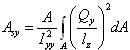
- ASY
- Specifies the shear area ratio in the y direction for Timoshenko beams. This quantity accounts
for shear deflection in the Y direction. This is defined as:
(1) 
- ASZ
- Specifies the shear area ratio in the z direction for Timoshenko beams. This quantity accounts
for shear deflection in the Z direction. This is defined as:
(2) 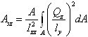
Qz is the first moment of cross-sectional area to be sheared by a force in the z direction. ly is the cross section dimension in the y direction. Izz is the area moment of inertia about the beam z-axis.
To neglect shear deformation in the z-direction, set ASZ=0. See Comment 14 for more information. ASZ > 0.
- cratio
- Defines the damping ratio for the beam. The beam damping matrix is calculated by multiplying the beam stiffness matrix with the cratio. In other words:
- preload_x, preload_y, preload_z
- Define a force in the X, Y, or Z direction(s) that is applied as a preload to the beam. The preload force that is specified will be applied to the beam element in addition to any forces computed along the X, Y, or Z directions during the simulation.
- preload_tx, preload_ty, preload_tz
- Define a moment about the X, Y, or Z axes that is applied as a preload to the beam. The preload moment that is specified will be applied to the beam element in addition to any moments computed about the X, Y, or Z directions.
Example
- Length of the beam = 57.55mm.
- Radius of circular cross section = 10mm.
- Material = steel.
- The damping ratio is 0.001.
The Force_Beam definition for these specifications:
<Force_Beam
     id                  = "7"
     i_marker_id         = "37"
     j_marker_id         = "47"
     length              = "57.55"
     E                   = "200000."
     G                   = "76923.08."
     area                = "314.1593"
     ixx                 = "15707.96"
     iyy                 = "7853.982"
     izz                 = "7853.982"
     ASY                 = "1.2"
     ASZ                 = "1.2"
     cratio              = "0.001">
</Force_Beam>
Comments
- The Timoshenko beam includes the effect of
the shear stresses on transverse deformation; the Euler-Bernoulli beam does
not. A constant shear over the beam height is assumed.
Figure 1 shows the definitions associated with a Force_Beam element.
- The x-axis of the J_Reference_Marker defines the neutral axis of the beam. The y- and z-axes of the J_Reference_Marker define the principal axes of the cross section. In other words, those directions along which the products of inertia Iyz = 0.
- At zero deformation, the
I_Reference_Marker is offset along the x-axis of
J_Reference_Marker by a distance equal to the free
length of the beam. It has the same orientation as
J_Reference_Marker.
The following forces act on the beam.
- Axial forces S1 and S7.
- Shear forces S2, S3, S8 and S9.
- Bending moments S5, S6, S11 and S12.
- Twisting moments S4 and S10.
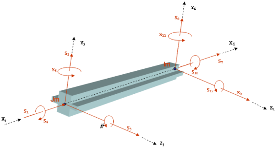
Figure 1. The definition of Force_Beam - The three angular deflections, AX(I,J), AY(I,J) and AZ(I,J) must remain small at all times. The angles AX(), AY() and AZ() lose physical significance otherwise, and the beam theory is no longer valid. Small means < 10 degrees.
- The stiffness matrix is calculated from the
inputs according to the following formulae:
(3) 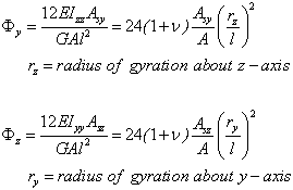
(rz/l) and (ry/l) are measures of the slenderness of the beam. For long and slender beams, this ratio is quite small, thus
 and
and
 can be taken as
zero. This is accomplished by setting Asy and
Asz to zero.
can be taken as
zero. This is accomplished by setting Asy and
Asz to zero.The stiffness matrix (see Przemieniecki, J.S., "Theory of Matrix Structural Analysis", Dover Publications, Inc., ISBN 0-486-64948-2, pages 70-82) can be computed from the physical properties as:
(4) - The forces acting at I and J are equal and opposite. Since there is a separation between J and I and the force does not act along the separation vector, the torque acting on body I is not the same as the torque acting on body J.
- The sign convention for the forces and
torques is as follows:
- A positive force tends to repel the I and J Reference_Markers. A negative force tends to attract the I and J Reference_Markers.
- A positive torque tends to rotate the I Reference_Marker in a counterclockwise direction, relative to the J Reference_Marker. Thus, a positive value of TX tends to increase the value of AX, TY of AY and TZ of AZ.
- Force_Beam is a linear element. If you wish to define a nonlinear force relationship, then use either the Force_Field or the Force_Vector_TwoBody modeling element.
- Force_Beam does not model warping, non-homogeneous material, curved beams or beams with non-uniform cross sections.
- Non-uniform cross sections can be modeled by a group of beams, each having different cross sectional properties.
- Figure 2
shows an exploded view of a Force_Beam acting between
two bodies. The exploded view is used to explain the implementation details
of a Force_Beam.
- Equations 1-4 show how the deformations are calculated.
- Equations 5-6 defines the force implementation.
- The last four equations, 7-10, show the forces and torques generated by the Force_Beam element are applied to the two bodies.
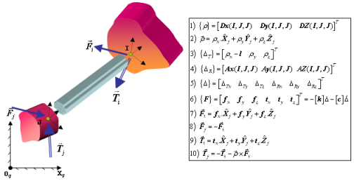
Figure 2. Implementation of a Force_Beam - When the cross section of the beam is not
circular, torsional loading on the beam causes the beam to twist. The
twisting causes the end sections to warp and radial lines do not
necessarily remain straight. The cross section resisting torsion is thus
reduced. The torsional shape factor has been calculated for commonly used
cross sections.
For more information, refer to "Formulas for Stress and Strain", Raymond J. Roark and Warren C. Young, McGraw-Hill Book Company. ISBN 0-07-053031-9; Table 20, pages 290-296.
- For beams with a small span/depth ratio,
in other words, with (rz >
0.3L) or (ry >
0.3L) shear stresses can cause significant
deflection and may in fact dominate the bending effects. The two factors
ASY and ASZ in the
Force_Beam statement account for shear deflection.
The table below shows typical values for ASY and
ASZ for cast iron.
- Cross Section
- ASY or ASZ
- Circular
- 1.2
- Rectangular
- 1.111 (10/9)
- Thin walled, hollow circular section
- 2.0
To obtain ASY and ASZ for other shapes or materials, refer to "Formulas for Stress and Strain", Raymond J. Roark and Warren C. Young, McGraw-Hill Book Company. ISBN 0-07-053031-9; Table 15, pages 200-201.