Constraint: Gear
Model ElementConstraint_Gear defines a gear constraint between two bodies.
Description
The gear is modeled as an algebraic relationship between input and output displacements between two joints. The inputs and outputs may be either rotational or translational. This allows spur, helical, bevel, and rack-and-pinion gear sets to be modeled.
Friction, back-lash, and manufacturing inaccuracies in tooth profiles are not modeled.
Format
<Constraint_Gear
     id             =   "integer"
   [ label          =   "string" ]
     joint1_id      =   "integer"
     joint2_id      =   "integer"
     cv_marker_id   =   "integer"
   [ is_virtual     =  {"FALSE" | "TRUE"} ]
</Constraint_Gear>
Attributes
- id
- Element identification number (integer>0). This number is unique among all Constraint_Gear elements.
- label
- The name of the Constraint_Gear element.
- joint1_id
- Specifies the first Constraint_Joint whose output is coupled by the gear
constraint.The parameter is mandatory. The joint type must be one of the following:
- Revolute
- Translational
- Cylindrical
- joint2_id
- Specifies the second Constraint_Joint whose output is coupled by the gear
constraint. The parameter is mandatory. The joint type must be one of
the following:
- Revolute
- Translational
- Cylindrical
- cv_marker_id
- Specifies a Reference_Marker whose origin defines the contact point. Its z-axis defines the direction of motion at the contact point. The parameter is mandatory. cv_marker_id must belong to the body containing the housing.
- is_virtual
- Defines whether the constraint is virtual or regular. If is_virtual is set to TRUE, the constraint is implemented as a virtual constraint. If is_virtual is set to FALSE, the constraint is implemented as a regular, algebraic constraint. This parameter is optional. The default is FALSE. See Comment 22 in Constraint: Joint for more information about virtual joints.
Example
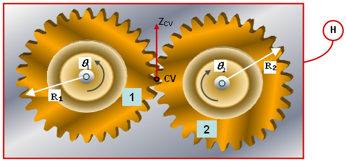 Figure 1. Defining a Spur-gear Set using CONSTRAINT_GEAR
Spur gear 1, with a pitch radius R1, is connected to the housing (shown as a red box) with Revolute Joint 1. It rotates about a fixed axis . Spur gear 2, with a pitch radius R2, is also connected to the housing with Revolute Joint 2 and it rotates about a fixed axis . Both axes are coming out of the plane of the paper.
The contact point between the two gears, shown as a red dot in the image above, is fixed with respect to the housing. It is defined by a Reference_Marker CV. The origin of CV defines the contact point and thus the velocity ratio of the gear set. The z-axis of CV points to the direction of motion at the contact point and therefore the direction of the contact forces at the teeth.
If the ID of the cv_marker, CV, is 1101. The Constraint_Gear object may be defined as:
<Constraint_Gear
     id            = "1"
     joint1_id     = "1"
     joint2_id     = "2"
     cv_marker_id  = "1101" >
</Constraint_Gear>
Comments
- The two joints, joint_1 and joint_2, must share a common body. This body is the housing. The cv_marker must belong to this body.
- The origin of the cv_marker defines the contact point between the two gears. The z-axis of the cv_marker defines the direction of motion at the contact point. It also defines the direction of the tooth forces. By pointing the z-axis along different directions, different types of gears may be modeled.
- The image below shows the location and
orientation of the cv_marker for a rack-and-pinion
constraint.
 Figure 2. cv_marker Definition for a Rack-and-pinion
Gear Set
Figure 2. cv_marker Definition for a Rack-and-pinion
Gear Set - The image below shows the location and
orientation of the cv_marker for a worm and worm-wheel
gear-set. The helical teeth on the worm impart a rotational motion to the
wheel.
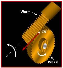 Figure 3. cv_marker Definition for a Worm and
Worm-wheel Gear Set
Figure 3. cv_marker Definition for a Worm and
Worm-wheel Gear Set