View Option Toggle Buttons
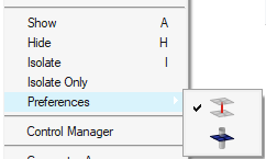
Figure 1.
Each button is modal, that is, you click it once to activate it, and click it again to deactivate it. Active buttons remain active until you specifically deactivate them, so you do not need to worry about them "resetting" after you perform an action such as isolate.
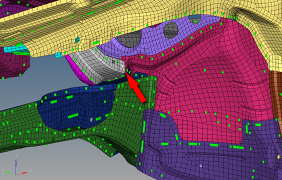
Figure 2. . Notice the small, white-highlighted connector entity on the grey-meshed part. (Model provided courtesy of Audi)
| Option | Name | Effect |
|---|---|---|
| Linked entity | Finds the link entities/supported entities to which the
selected connector connects. If this linked entity view option button is active, all entities linked to the 1st connector entities will be taken into account for the action. It does not matter if the 1st connector entity view option button is active or inactive, its entities will still be located. This determination has nothing to do with any display states. This means that in case of isolation, only the
entities which are referenced by the selected connectors
(1st connector entity) are isolated.
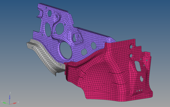 Figure 3. . The connector does not display because "1st linked entity" is not active. |
|
| Realization | Finds and displays the realization for the selected
connectors.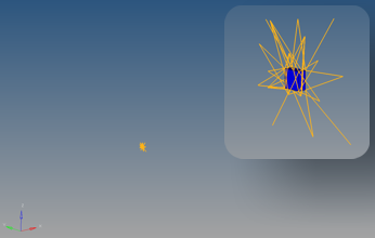 Figure 4. |
Cumulative Effect of Multiple View Options
These options work accumulatively, for example, when both the Linked entity and 2nd connector entity buttons are active, then selecting and isolating a connector displays the component that it links to, and all the other connectors that link to that component. If you had Realization, Linked entity, and 2nd connector entity active when you isolated the same connector, then the model would display the component to which the connector links, all other connectors linking to that component, and the realizations of each displayed connector.