Mass Trimming Browser
Use the Mass Trimming tool to create, define and realize mass entities.
From the menu bar, click .
Mass entities are used to define mass distribution. A mass entity stores information like the mass value, method of distribution, NSM, Point Mass, or Rigid mass with a mass center, and attached locations and realization types. These definitions are not associated with physical FE entities. If all of the FE entities in the model are deleted, the mass information will still be maintained. Mass entities can be saved in an HyperMesh binary file which can be imported into a new FE model and realized.
Mass Trimming Tool Interface
The Mass Trimming tool opens in the browser area.
The toolbar at the top of the Mass Trimming tool consists of tools used to create mass entities and control their display state.
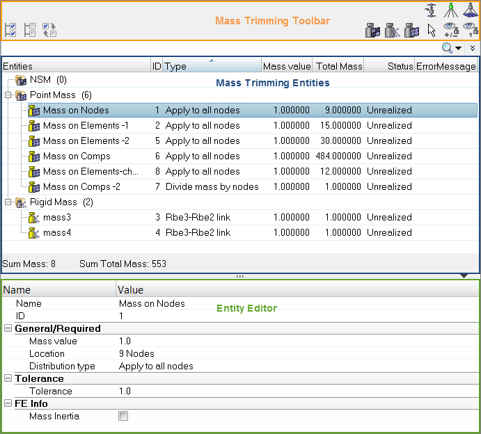
Figure 1.
| Tool | Description |
|---|---|
 |
Creates an NSM mass. |
 |
Creates a Rigid mass. |
 |
Creates a point mass. |
| Interactively select any type of supported mass entity via
the browser, or by selecting within the
graphics area. The Selector can be used to find mass entities
from the graphics area which will then be highlighted in the
list. This is an efficient way of selecting multiple mass
entities at once. This tool can be used in conjunction with the Show, Hide, Isolate, and Isolate Only tools. |
|
 |
Show/hide selected mass entities. Alternatively, click this
mode on and then pick the desired mass from the graphics
area; masses and any other entities determined by the view
option toggle settings are hidden as you click on
them.
Note: When used to select from the graphics area,
this button only works on visible
connectors.
|
 |
Isolate/isolate only selected mass entities. Alternatively, click this mode on and then pick the desired mass entity from the graphics area. |
 |
Opens the Perform FeAbsorb dialog, from which you can add (absorb) certain FE information into mass entities. |
 |
Finds and displays the realized FE for the selected mass entities. |
 |
Finds the entities attached to the selected mass entity. When this tool is active, all entities attached to the selected mass entity will be taken into account when a display change is performed. |
Context Menu
Supported Entities
- NSM ()
- A non-structural mass that can be distributed to elements, properties, and components, and defines/updates the required solver cards. A group entity is created for each mass entity. The group entity can be assigned a NSM1 or NSML1 card depending on the distribution method chosen. Only supported in OptiStruct and Nastran user profiles.
- Rigid ()
- A mass that takes the form of a mass element connected to nodes with rigid elements (Multiple RBE2, RBE3/RBE2, and so on).
- Point ()
- A single mass element that is created at each selected node. A value is computed based on the distribution method.
Mass Entity States
- unrealized (
 )
) - The initial definition of the mass entity after it is created. Unrealized masses are displayed yellow.
- realized (
 )
) - The mass is considered realized only if weld creation at the mass was successful. Realized masses are displayed green.
- modified (
 )
) - The mass is considered modified when one or more of its corresponding attributes have been edited in the Entity Editor. Modified masses are displayed blue.
- failed (
 )
) - The mass is considered failed if the weld creation at the mass was not successful. Failed masses are displayed red.
Manage Mass Entities
Create, define and realize mass entities.
Create Mass Entities
- In the browser, right-click and select Create from the context menu.
- Click the Create Mass tool for the appropriate mass type on the toolbar.
Define Mass Entities
Define mass entities in the Entity Editor.
You can modify the distribution type, mass value, and total mass in the Mass Trimming Browser.
- In the Mass Trimming Browser, select the mass to define.
- In the Entity Editor, define the mass.
Mass Attributes
Supported attributes for Mass entities.
NSM Mass
- Mass value
- Mass value to be distributed.
- NSM Distribution type
-
- Total Mass. A NSML1 card is created with either an element set or a property set that is based on the NSM entity type definition.
- Per unit area/length.
- Property type
- Type of elements or properties used to distribute the mass. Supported property types include PSHELL, PSHEAR, and PCOMP.
- Location
-
- If NSM entity type is Elements, than elements can be selected in the model and element set will be created for the NSM solver card.
- If NSM entity type is Properties, than properties can be selected in the model and a property set will be created to realize the mass entity.
- Reconnect rule
Rigid Mass
- Calculate node
- Calculates the mass location at the CG of the attachment points.
- Mass value
- Mass value to be put at the mass center.
- Realization type
-
- RBE2. The mass takes the form of a mass element connected to nodes with rigid elements (multiple RBE2).
- RBE2 link. The mass takes the form of a mass element connected to nodes with a rigidlink element (single RBE2).
- RBE3. The mass takes the form of a mass element connected to nodes with a RBE3 element.
- RBE3-RBE2. The mass takes the form of a mass element connected to nodes with a RBE3 element connected to RBE2.
- RBE3-RBE2 link. The mass takes the form of a mass element connected to nodes with a RBE3 element connected to RBE2 link.
- Location
- Position at which the mass is created. If the calculate node option is not selected, then a location for mass center will need to be selected.
- Attachment point
- To define the attachment points, nodes have to be selected in the
model. Node selection is not used as is. A search is performed to see
what is attached to the nodes.
- If a node is selected on a hole, then the center of the hole will become the attachment location. If multiple nodes on a hole are selected, they will still treated as one attachment.
- If a node is selected on a mesh, then the nodes of the attached elements (shell or solid) will be selected.
- If two or more nodes are selected in close proximity and the attached elements are adjacent, then the entire patch will be selected.
- If an independent node of a rigid is selected, then the independent node is selected for the attachment. The second leg is not created for two level rigid masses, such as RBE3-RBE2 or RBE3-RBE2 links. The first leg is terminated at the independent node.
- If the free end of a CBUSH, with or without a tag, is attached to a rigid on the other end, then the second leg is not created and the rigid type mass is terminated at the first leg.
- Attached Location Tolerance
- Tolerance value used to search for nearby FE entities to attach.
- Realization zone
- Only available when the attachment is on a hole.
- Inside. Use the nodes of the holes.
- Outside. Use the node from the elements that form the hole, without the hole nodes.
- Inside/outside. Use the nodes of the elements at the hole.
- Mass Inertia
- Rbe2/Rbe2 link
- Realized FE in
-
- Auto
- Realized FE to current comp
- Realized FE to selected comp
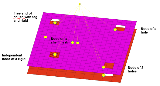
Figure 2. Nodes Selected for Attachment Points
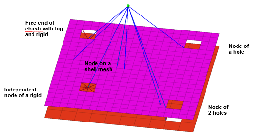
Figure 3. Manual Mode for Single Level Rigid Creation. In this mode, only the selected nodes are used to define the rigid.
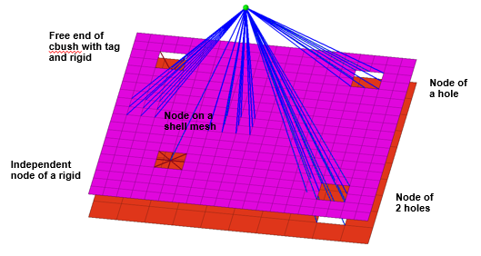
Figure 4. Automatic Mode for Single Level Rigid Creation. If the Manual option is not enabled in the Entity Editor, the nodes of adjacent elements will be used to define the rigid if the selected nodes are on a hole or are nodes on a mesh.
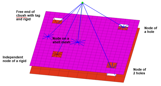
Figure 5. Two Level Rigid. In the case of a two level rigid, Automatic and Manual mode is not available. Instead, input nodes are processed. If input nodes are on a hole, then the nodes of the hole are used. If the realization is set to inside or inside/outside, then washer nodes are used. When the input node is an independent node or the free end of a cbush attached to a rigid, then the second level rigid will not be created. The RBE3 from the conm is terminated at these nodes.
Point Mass
- Mass value
- Mass value to be used for defining point masses.
- Location
- Position at which the mass is created. Can be nodes, elements, properties, or components. For elements, only shell elements are supported.
- Distribution type
-
- Apply to all nodes
- Divide mass by nodes
- Divide mass by area (Not available when Location is defined by Components or Properties)
- Unit area distribution (Not available when Location is defined by Components or Properties)
- Tolerance
- Tolerance value used to search for nodes to create point mass elements. point mass on nodes, the tolerance value is used for a spherical search.
- Threshold for Element Remapping(+-%)
- When the old area and tolerance are used to search in the new mesh, the remapping may not always give 100% of the old area based on mesh size and pattern. A % value like +-10% will allow you to successfully remap and realize if the difference in area is within 10%.
- Mass Inertia
- Realized FE in
-
- Auto
- Realized FE to current comp
- Realized FE to selected comp
Limitations
- For NSM and Point masses defined on elements, if the mass entity is in an unrealized state and partial elements are deleted, then upon rerealization, the status will be failed. If you translate the nodes of the elements and try to realize again, the graphics may be misleading because the failed locations might not reflect the translated location. However, re-realization with appropriate threshold values or a reconcile will work properly.
- For NSM and Point masses defined on elements, if the mass entity is saved as an Engineering Solutions file and realized in a new design that has coincident elements in the same area, then both elements will be selected which will result in an increase of area of elements; hence the mass entity will fail, showing a new threshold value that is needed in order to realize properly. In such cases, the duplicate elements have to be deselected for those mass entities.
- For Rigid masses in automatic mode, if a node on a hole is selected, then the nodes of the hole will be automatically selected. However, if the node is on the boundary of a mesh, then the nodes of the entire boundary will be selected even though it is not a hole. In automatic mode, it is advised that you do not select boundary nodes.
- When performing FE-Absorb on Rigid masses, a rigid mass might be absorbed as a mass entity, and the realization might fail if the attachment point is not supported. For example, if the Rigid from a CONM2 mass is connected to a dependent node of another Rigid, FE-Absorb will absorb this as a mass entity. Re-realization will fail because only the independent node is supported as a valid node and not a dependent node.
- For Rigid masses, Rigids will be absorbed during FE-Absorb as a Mass entity when they are connected to spring elements of any type, and a Rigid will be created during re-realization. If the FE model is deleted from the current session, realization will fail when you try to reapply the Trim mass to a new model, and a graphics message that reads “CBUSH node” will be displayed. At this point, you will only be able to reconnect to CBUSH spring elements.
Realize Mass Entities
Resolve Failed Connections
Execute the search order to resolve failed connections.
-
You can execute a search order to find alternate connection methods at failed
locations. The search order provides the following options which can be selected
and ordered in the sequence it is desired.
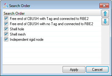
Figure 6.If you execute the search order, an alternate attachment method will be searched based on the tolerance in the sequence defined and establish connection at the failed locations. At this point, the new method will be saved for sub-sequent realizations. If within the tolerance, the search order does not find an alternate attachment method, then the status will remain failed. However, if after the search order is executed, and alternate attachment methods are established within the tolerance, then the status will turn to yellow and the mass entity can be realized.
- In the original mesh, the attachment type is a node on a shell mesh which
finds nodes of adjacent elements to create the second level rigid.
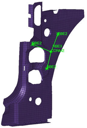
Figure 7. - When the mesh is deleted and realized, the realization fails. The modeling window indicates what it is looking for at those
attachment locations.
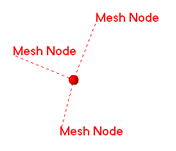
Figure 8. - When importing a new mesh, there is no shell mesh near the attachment within
the tolerance at two locations; however, there is a hole and an independent
node. After realizing, the mass fails at the two locations.
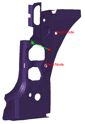
Figure 9. - Executing a search order with the following settings finds alternate
attachment methods. The search order is set to first look for independent
node. If no independent nodes are found it will then look for a shell mesh.
The other options are not selected.
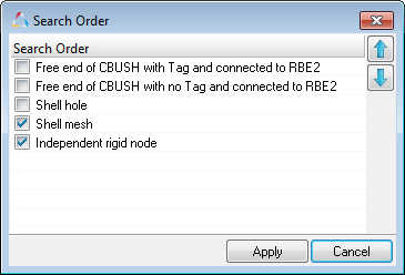
Figure 10. - The image below shows the alternate attachments that were found at those
locations, which are realized.
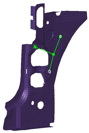
Figure 11. - If the mesh is deleted and realized again, the new attachment method will be
used for sub-sequent realizations. The original attachment method was node
on a mesh at all three locations, but after executing the search order on
the new mesh, the attachment methods change.
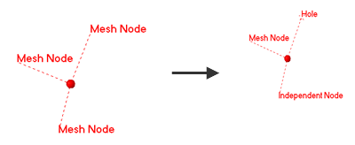
Figure 12.
Perform FE Absorption
For FE models, use FE-Absorb to absorb the Trim Mass into the Mass entity.
During FE Absorption, you can only use realization types that are supported by the Mass Trimming tool. For second level rigids that cannot be absorbed completely, the independent node will be used as the attachment node.
Rigid Mass
-
In the Mass Trimming Browser, click on the toolbar.
The Perform FEAbsorb dialog opens.
-
Click FeAbsorb.
In the image below, the second level leg is attached to the node surface of the solid hole, which is not supported during the realization process. The second leg will instead be used to absorb the attachment to the independent node. A second level spider will not created during realization.
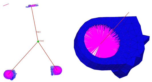
Figure 13.
Point Mass
-
In the Mass Trimming Browser, click on the toolbar.
The Perform FEAbsorb dialog opens.
NSM Mass
-
In the ,Mass Trimming Browser click on the toolbar.
The Perform FEAbsorb dialog opens.