Contact Browser
Use the Contact Browser to create, review and modify contact interfaces and surfaces in a model.
From the menu bar, click .
Contact interfaces and surfaces can be imported, created manually, or generated automatically using the AutoContact option. Upon importing a solver deck or Engineering Solutions model, existing contacts are created and populated in the Contact Browser. Contact interfaces and surfaces are organized into their respective folders in the browser.
Browser Interface
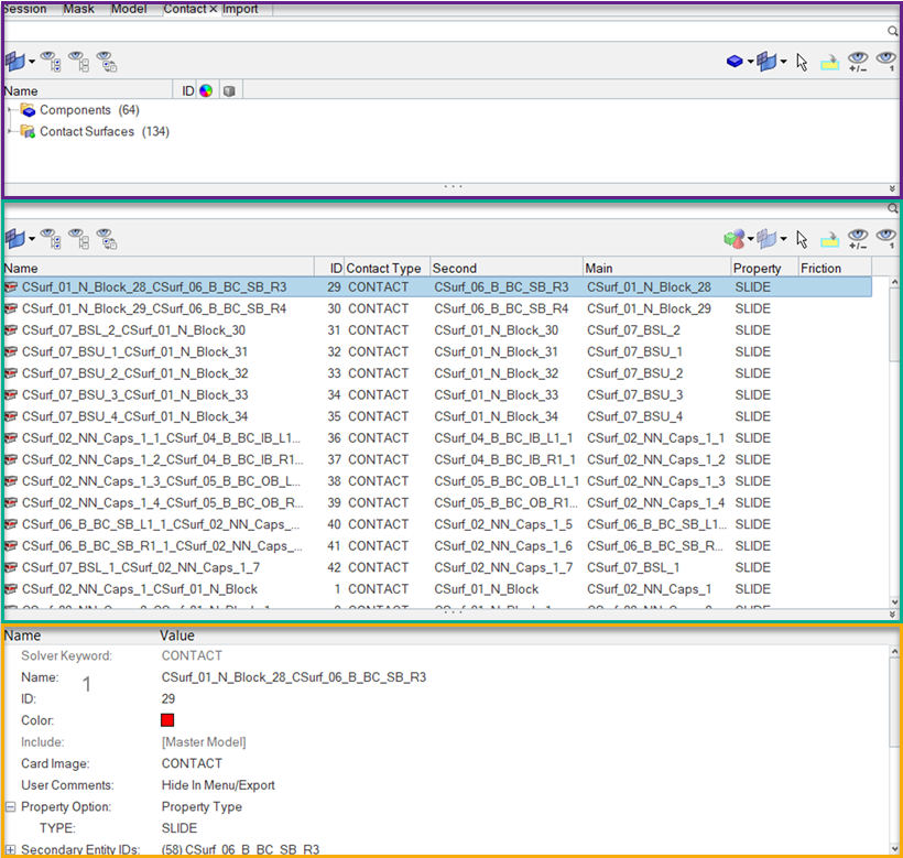
Figure 1.
Create Contacts
Create Contacts Manually
In the Contact Browser you can manually create contacts.
-
Define additional entity parameters and properties accordingly.
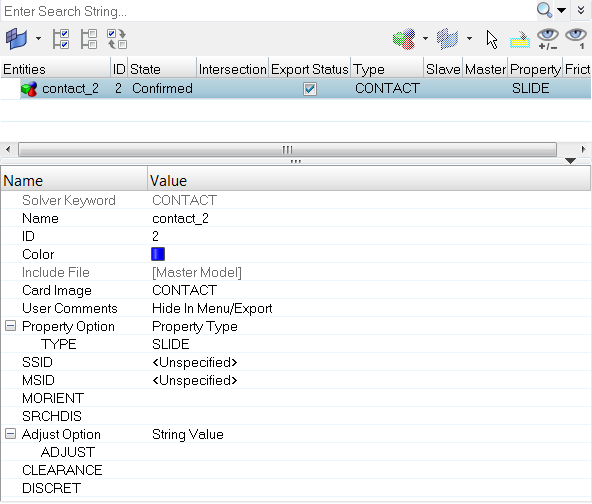
Figure 2. . Contact Browser and Entity Editor in the OptiStruct user profile.
Generate Contacts Automatically
Auto contact generation works independent of whether the model is FE or geometric. When you elect to generate contacts automatically, contact bodies are detected and contact pairs and contact sets are created.
-
Click Create.
Based on a vicinity tolerance, the AutoContact tool searches throughout all of the selected components and automatically creates new Contact interfaces and contact surfaces between them. All the objects created are populated in the Contact Browser into their respective folders.
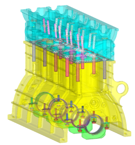
Figure 3.
AutoContact Logic
The following logic applies in the selection of surfaces for AutoContact in the order it is written.
- The surface of the component or element set defined as rigid body, and the surface defined as rigid surface, will always be a main surface.
- The surface of a component, or an element set with coarser mesh, will be a main surface.
- The surface of a component, or an element with less stiffness in comparison with the mating surface, will be a secondary surface.
- The larger surface will be identified as a main surface.
Modify Contact Interfaces and Surfaces
The Contact Browser lists every contact interface and surface within a Engineering Solutions session and organizes them into their respective folders. You can modify these contact interfaces and surfaces using the Entity Editor.
-
In the Contact Browser, click a contact interface or
surface.
The Entity Editor opens and displays the entities corresponding data.Note: If you select multiple entities in the browser, the Entity Editor displays the selected entities common corresponding data. The rows that contain ### indicate that these fields do not contain common data but can still be modified. When you modify the data, both common and ambiguous, Engineering Solutions applies the changes to all of the selected entities. To select multiple entities, left-click entities while pressing Control.
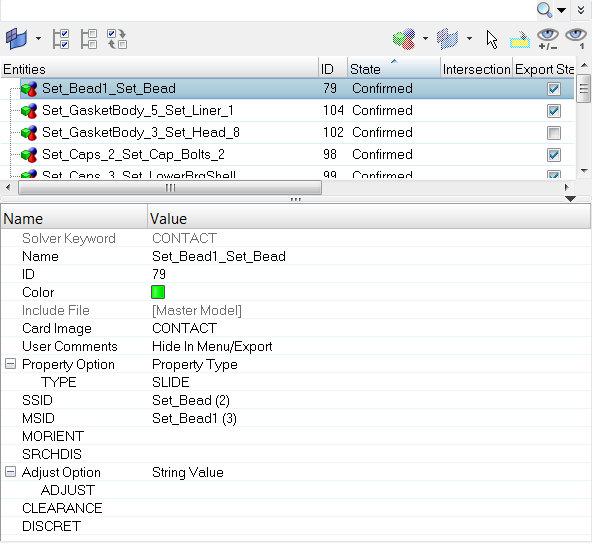
Figure 4.
Solver Specific Details
Abaqus
- The Contact Browser supports the following contact and
constraint definitions for Standard and Explicit profiles of Abaqus:
- AutoContact
- Contact pair
- General contact
- Contact Tie
- Shell to Solid coupling
- The AutoContact option creates contact pairs and tie constraints depending on whether you set Contact Type to Contact or Tie.
- While using AutoContact, you can specify to have the secondary surface be created as a node-based surface.
- All contact pair definitions in Abaqus will
require a surface interaction definition.
- AutoContact creates a surface interaction property with default solver behavior.
- You can choose an existing surface interaction to be used for contact pairs recognized by AutoContact.
- AutoContact can create contact pair/tie with review status before confirming.
- In the contact information pane (middle pane in the browser), you can interactively add friction, adjust, and specify other optional parameters.
- Use Advanced delete to delete contact pair/tie. The corresponding main and secondary surfaces and surface property are used for the contact pair unless the surface property is otherwise specified to be used in other contact pair definitions.
ANSYS
- Creating and managing contact surfaces and pairs is handled by the Contact Browser.
- Both manual contacts and AutoContact options are available. The AutoContact option can be used to create Surface to Surface contacts.
- Before creating contact pairs in Engineering Solutions, it is recommend that you know which ANSYS contacts are supported in Engineering Solutions.
- ANSYS contact regions are modeled like ordinary FE elements over the regions of FE models that represent the geometry. In ANSYS terms, both CONTACT and TARGET surfaces are sets of elements at contact regions. Prior to Engineering Solutions 14.0.130, the ANSYS interface supported the same principle as ANSYS, therefore both CONTACT and TARGET regions were elements over model geometry in Engineering Solutions.
- Starting in Engineering Solutions 14.0.130, both contact and target regions are identified as CONTACT SURFACES. A pair of contact and target surfaces which interact with each other in analysis are GROUPS. You need to create contact surfaces for both CONTACT and TARGET regions. They will then be paired together under groups to successfully define the contacts. ANSYS solver files (*.cdb files) with contacts are imported into Engineering Solutions, and identify the contact regions from the contact elements to show the regions as contact surfaces. Contact pairs can be seen in groups.
- During export, Engineering Solutions creates contact elements from the contact regions and exports them as elements. In ANSYS, they are explained above elements with contact element type.
- The Contact Browser currently supports the creation of
edge to edge, surface to surface, and point o surface contacts with pilot
node and symmetry contact options.
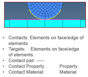
Figure 5. HyperMesh 14.0.120 and Earlier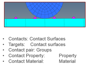
Figure 6. HyperMesh 14.0.130
Nastran (MSC)
- The AutoContact option will create new contact cards using their default values.
- When reading legacy models (.bdf, .dat and .hm), old contacts will be mapped to new contact cards.
- Contact parameters in the BCTABLE card are mapped to equivalent contact properties (BCONPRP and BCONPRG) in new contact cards.
- Properties associated with BCPROP should be assigned to either elements or respective components in the contact card.
- You can export old contact cards by enabling the Export old Contact Card checkbox, which can be accessed in the in the Export-Solver Deck Browser when you click Select Options.
- The Contact group entity is mapped to the BCTABL1 solver card.
- The BCTABL1 solver card contains a list of contact pair (BCONECT) cards.
- The AutoContact option will create a BCONECT card for each pair, and group all pairs in the BCTABL1 card.
- BSURF and BCBODY1 solver cards are remapped from group entities to set entities.
- BSURF and BCBODY1 are combined into one entity. Input for BCBODY1 can be defined in the BSURF card with the Entity Editor.
Nastran (NX)
- The Contact group entity is mapped to the BCTADD/BGADD solver cards.
- The BCTADD and BGADD solver card contains a list BCTSET and BGSET cards respectively.
- The AutoContact option will create BCTSET/BGSET card for each pair, and group all pairs in the BCTADD/BGADD solver card.
- BSURF and BCRPARA solver cards are combined into one entity and migrated from group entity to set entity. BSURF defines the contact region using shell elements.
- BSURFS and BCRPARA are combined into one entity and migrated from group entity to set segment entity. BSURFS defines the contact region using solid elements.
- Input for BCRPARA can be defined in the BSURF/BSURFS card with the Entity Editor.
- BGPARM, BCTPARM, BCTPARA are migrated to property entity. BGPARM is valid only for glue contact BGSET and BCTPARM/BCTPARA are valid only for friction contact BCTSET.
- Subcase dependent contacts can be defined through the case control card under subcase options in the loadstep entity.
OptiStruct
- The Contact type, Contact, creates a contact pair, and the Contact type, Tie, creates a Tie contact.
- Master ID and Slave ID types will be as per solver default Set of elements for master ID and Set of nodes for slave ID.
- Auto contact will honor the entity type in Master and Slave entity type.
- Master entity types have the following mutually exclusive options: Set of elements or SURF. Similarly Slave entity type will have Set of nodes, Set of elements, and SURF. You can only select one of the entities.
- The Contact property option is only available when the Contact type is Contact.
- You can assign Contact contacts a Property type (SLIDE, STICK, FREEZE), a Static Friction Coefficient, or an existing property (PCONT).
Context Menu
- Review
- Highlights the secondary and main surfaces in two different colors,
while the rest of the model is transparent and gray.
Figure 7. - Show
- Displays the contact's main and secondary surfaces in their assigned colors. The rest of the model display is left unchanged.
- Hide
- Turns off the display the contact's surfaces. The rest of the model display is left unchanged.
- Isolate Only
- Fits the selected contact to the graphics area, and displays the secondary and main bodies in two different colors. The rest of the model is turned off.
- Swap Master-Slave
- Switches the contact surfaces identified as master and slave. Upon selecting Swap Master-Slave, the surfaces switch from places in the master to slave positions in the browser.
- Swap Cp-Tie
- Changes the type of interface created. A surface interaction is required for Contact Pairs but not for a Tie, therefore any surface interaction identified earlier will be lost upon swapping from CP to TIE. If you switch back from TIE to CP, the surface interaction will not be retained.
- Reverse Normals
- Flips all the normals of selected elements or surfaces.
- Display Normals
- Displays the normals of selected elements or surfaces as vectors or in color mode.
- Display Base Element Normals
- Displays the normals for parent elements of the surface.
- Normals Off
- Turns off normals if they are displayed.