Indoor LTE with MIMO Distributed
Perform indoor network planning for long term evolution (LTE) using multiple input multiple output (MIMO).
Model Type
The model consists of an office building where wireless connectivity using MIMO technology is investigated.
Sites and Antennas
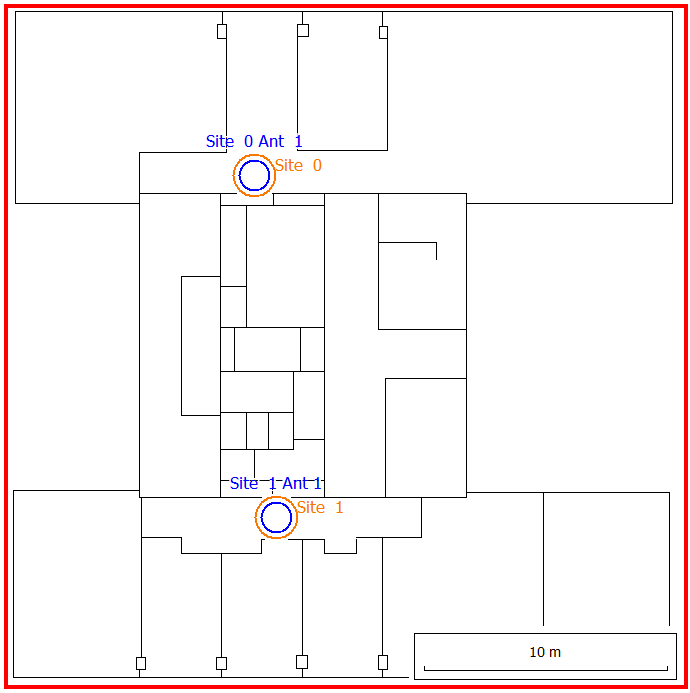
Figure 1. Building with two widely-spaced MIMO antennas.
Air Interface
The air interface is defined by an LTE wireless standard in LTE_Sample_Indoor_MIMO_Distributed.wst. Orthogonal frequency division multiple access (OFDM/SOFDMA) is the multiple access scheme selected for this air interface. Two-streams MIMO technology is used. Overhead and interference associated with having the two MIMO streams on the same carrier frequency are specified here. Frequency division duplex (FDD) separation between uplink and downlink is set to 190 MHz.
A list of different modulation and coding schemes are found on the Air Interface tab, under Transmission Modes (MCS). Overhead and interference associated with having two MIMO streams on the same carrier are specified here.
Computational Method
Results
Propagation results show at every location the power received from each transmitting antenna. Results are available for a single prediction plane at a height of 1.5 m.
Network-planning results include maximum data rate, maximum throughput, and number of MIMO streams for both the uplink and downlink. These results can be viewed by selecting Results: Network in the result tree. It is not advantageous to have two MIMO antennas separated by a large distance while operating on the same carrier and transmitting individual streams. In the area between the antennas, the SNIR is often low (their interference is high) and communication may not be possible.
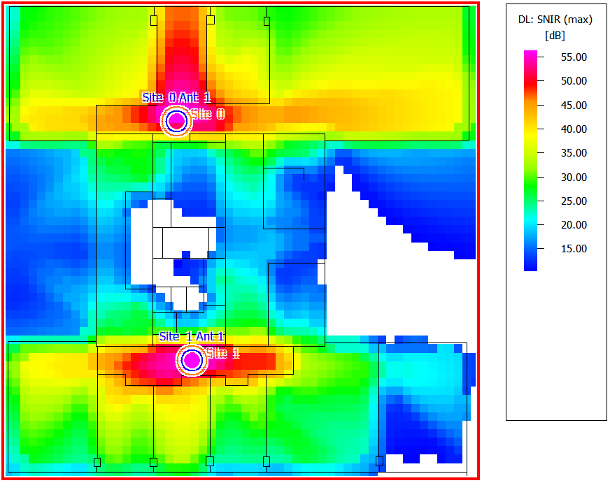
Figure 2. An example of SNIR in a scenario where the MIMO antennas are placed far apart.