/SHELL
Block Format Keyword Describes input for 4-node shell elements.
Format
| (1) | (2) | (3) | (4) | (5) | (6) | (7) | (8) | (9) | (10) |
|---|---|---|---|---|---|---|---|---|---|
| /SHELL/part_ID/unit_ID | |||||||||
| shell_ID | node_ID1 | node_ID2 | node_ID3 | node_ID4 | Thick | ||||
Definitions
| Field | Contents | SI Unit Example |
|---|---|---|
| part_ID | Part identifier of the block (Integer, maximum 10 digits) |
|
| unit_ID | Optional unit identifier. (Integer, maximum 10 digits) |
|
| shell_ID | Element
identifier (Integer) |
|
| node_ID1 | Node identifier
1 (Integer) |
|
| node_ID2 | Node identifier
2 (Integer) |
|
| node_ID3 | Node identifier
3 (Integer) |
|
| node_ID4 | Node identifier
4 (Integer) |
|
| Orthotropy angle to element skew. 5
(Real) |
||
| Thick | Shell thickness By default, this shell has the thickness given in the property set prop_ID of the part part_ID. (Real) |
Comments
- The identifier must be unique in each element family, but it is advised for each element type to have a unique element identifier in the global model.
- More than one shell block can be used to define a part.
- Any number of shells can be defined in one block.
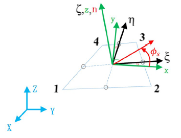
- For Coordinate system in 3-node shell element, refer to Radioss Coordinate System in the User Guide.
- If def_orth = 1, the
orthotropy angle,
is only used in /PLY
and /PROP/TYPE19 (PLY).

Figure 1.