Rigid Body (/RBODY)
A rigid body is defined by a set of secondary nodes and a main node. It can be compared to a part with an infinite stiffness. No relative displacement is allowed between secondary nodes, and the general motion of the rigid body manages the main node.
As a kinematic condition is applied on each secondary nodes and for all directions, no other nodal constraint is allowed. However, in the case of the Lagrange Multiplier method, the solution can be found if no incompatible kinematic conditions are applied.
- Case 1:
- COG is computed with secondary and main nodes mass and coordinates
- Case 2:
- COG is computed with secondary nodes mass and coordinates only
- Case 3:
- COG is set at main node's coordinates
- Case 4:
- COG is set at main node's coordinates
It is strongly recommended to use an artificial node (not part of an element) as a main node, since Radioss Starter is likely to move the main node. The main node is moved by Radioss Starter to the center of gravity; unless the ICoG flag is set to 3 or 4. It is advised to set ICoG to 2 to get the most realistic behavior; the center of gravity is then computed taking into account only the secondary nodes. If ICoG is set to 1, the main node, with its own mass, is included to compute the center of gravity.
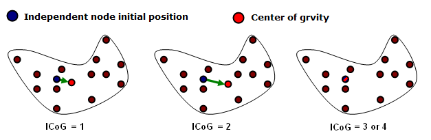
Figure 1. Center of Gravity Computation
- Rigid body covering a part of a finite element model, including shells, solids or other elements: In this case, the mass of secondary nodes gives the total rigid body mass and no added mass is needed. The main node can be located anywhere, and it will be moved to the center of mass. This kind of rigid body saves a large amount of CPU time.
- Rigid body representing a non-modeled component connected on some structural nodes: In this case, only a few number of secondary nodes are used to connect the rigid body to the finite element model. The mass and inertia are added and the main node is located at the component center of mass. The main node will only move a little, taking into account the mass of the secondary nodes. In some cases, a dummy mesh is used to visualize the rigid body or to simulate the contacts, but if the dummy elements have a small mass, the previous remarks are still true.
- Rigid body used to connect two or more parts together: For these rigid bodies no added mass is needed and the main node can be located anywhere. A spherical inertia must be used for these rigid bodies; as these rigid bodies are usually very small (4 to 8 nodes), the inertia is often very small in one direction and very large for one specific direction. This may lead to instability; therefore, through the use of spherical inertia, inertia will be identical for any direction.
Activation/Deactivation
Rigid bodies can be activated or deactivated with /SENSOR or using the /RBODY/ON or /RBODY/OFF Engine options.
- /RBODY/ON
- 1 2
- /RBODY/OFF
- 3
Rigid Body Motions
One of the main uses of rigid body activation and deactivation concerns the roll-over motions, as in roll-over simulations. During the free flight of the car, the elements deformation can be neglected. A large part of CPU time can be saved if the whole structure is replaced with a temporary rigid body during the fly. Before the impact on the ground, this rigid body is deactivated and eventually activated again after rebound.
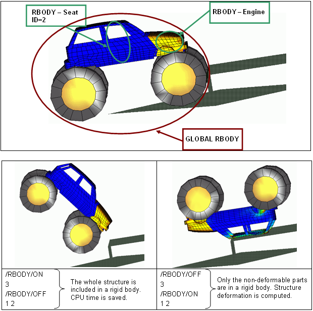
Figure 2. Activation - Deactivation of Rigid Bodies in a Roll-Over Example
Initial Static Equilibrium
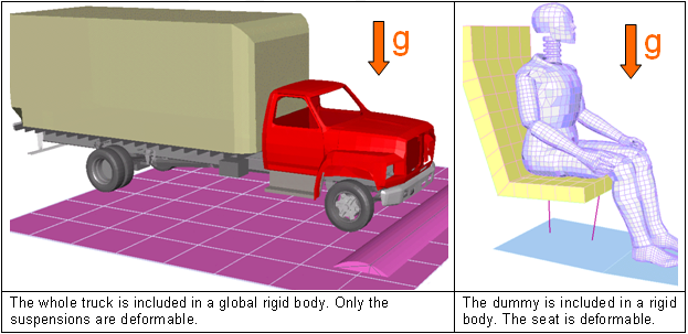
Figure 3. Static Equilibrium Examples
Merge Rigid Bodies
The /MERGE/RBODY option can be used to merge rigid bodies together or add secondary nodes to an existing rigid body. The secondary entities defined become secondary to a main rigid body. The secondary entities can be rigid bodies, single nodes, or node sets. Multiple secondary entities can be merged into one main rigid body by defining multiple lines in /MERGE/RBODY.
Some use cases include merging two different assemblies defined in two separate include files by defining the merge in the main input file. This can also be useful when separate parts defined as rigid need to be merged into one rigid body to model a complex component like an engine.
The main rigid body defined in /MERGE/RBODY can be defined as a secondary rigid body in another /MERGE/RBODY. However, complex hierarchies should be avoided as they can become difficult to debug. The secondary entities can only be defined in one /MERGE/RBODY and not in any /RBODY; otherwise, incompatible kinematic conditions occur.
Before merging, the inertia, mass, and center of gravity of each the secondary and main rigid body is calculated based on their /RBODY properties. Next, the secondary entities are merged to the main rigid body and new rigid body properties are calculated based on the /MERGE/RBODY Iflag option.