/DTPL
Optimization Keyword Defines parameters for the generation of topology design variables.
Format
| (1) | (2) | (3) | (4) | (5) | (6) | (7) | (8) | (9) | (10) |
|---|---|---|---|---|---|---|---|---|---|
| /DTPL/dtpl_ID | |||||||||
| title | |||||||||
| grpart_ID | TMIN | STRESS | MEMBSIZ | PATRN | PATREP | EXTR | MESH | DRAW | MMOCID |
| (1) | (2) | (3) | (4) | (5) | (6) | (7) | (8) | (9) | (10) |
|---|---|---|---|---|---|---|---|---|---|
| T0 | |||||||||
| (1) | (2) | (3) | (4) | (5) | (6) | (7) | (8) | (9) | (10) |
|---|---|---|---|---|---|---|---|---|---|
| MAXSTRS | |||||||||
| (1) | (2) | (3) | (4) | (5) | (6) | (7) | (8) | (9) | (10) |
|---|---|---|---|---|---|---|---|---|---|
| MINDIM | MAXDIM | MINGAP | |||||||
| (1) | (2) | (3) | (4) | (5) | (6) | (7) | (8) | (9) | (10) |
|---|---|---|---|---|---|---|---|---|---|
| TYP | AID | XA | YA | ZA | |||||
| FID | XF | YF | ZF | ||||||
| UCYC | SID | XS | YS | ZS | |||||
PATREP=0/1/2,
| (1) | (2) | (3) | (4) | (5) | (6) | (7) | (8) | (9) | (10) |
|---|---|---|---|---|---|---|---|---|---|
| ptrepCID | |||||||||
| CAID | XCA | YCA | ZCA | ||||||
| CFID | XCF | YCF | ZCF | ||||||
| CSID | XCS | YCS | ZCS | ||||||
| CTID | XCT | YCT | ZCT | ||||||
| (1) | (2) | (3) | (4) | (5) | (6) | (7) | (8) | (9) | (10) |
|---|---|---|---|---|---|---|---|---|---|
| mainID | SX | SY | SZ | ||||||
| ptrepCID | |||||||||
| CAID | XCA | YCA | ZCA | ||||||
| CFID | XCF | YCF | ZCF | ||||||
| CSID | XCS | YCS | ZCS | ||||||
| CTID | XCT | YCT | ZCT | ||||||
| (1) | (2) | (3) | (4) | (5) | (6) | (7) | (8) | (9) | (10) |
|---|---|---|---|---|---|---|---|---|---|
| ETYP | extrGRN1 | extrGRN2 |
| (1) | (2) | (3) | (4) | (5) | (6) | (7) | (8) | (9) | (10) |
|---|---|---|---|---|---|---|---|---|---|
| MTYP |
| (1) | (2) | (3) | (4) | (5) | (6) | (7) | (8) | (9) | (10) |
|---|---|---|---|---|---|---|---|---|---|
| DTYP | DAID | XDA | YDA | ZDA | |||||
| DFID | XDF | YDF | ZDF | ||||||
| ogrpart | NOHOLE | TSTAMP | |||||||
| (1) | (2) | (3) | (4) | (5) | (6) | (7) | (8) | (9) | (10) |
|---|---|---|---|---|---|---|---|---|---|
| MCID |
Definitions
| Field | Contents | SI Unit Example |
|---|---|---|
| dtpl_ID | Topology design
variable identifier. (Integer > 0) |
|
| title | Title. (Character, maximum 100 characters) |
|
| grpart_ID | Part group
identifier defining the design space. (Integer > 0) |
|
| TMIN | Indicates if
minimum thickness definition is defined.
(Integer) |
|
| T0 | Minimum
thickness. (Real > 0.0) |
|
| STRESS | Indicates if the
von Mises stress constraint is to be defined.
(Integer) |
|
| MAXSTRS | Upper bound of the
constraint on von Mises stress. No default (Real > 0.0) |
|
| MEMBSIZ | Active Member Size Control
flag.
(Integer ≥ 0) |
|
| MINDIM | Specifies the
minimum diameter of members formed. This field can be used
to eliminate small members. It also eliminates checkerboard
results. Default = No Minimum Member Size Control (Real > 0.0) |
|
| MAXDIM | Specifies the
maximum diameter of members formed. This field can be used
to prevent the formation of large members. It can only be
used in conjunction with
MINDIM. Default = No Maximum Member Size Control (Real > 0.0) |
|
| MINGAP | Defines the minimum
spacing between structural members formed. This command can
only be used in conjunction with
MAXDIM. Default = blank (Real > MAXDIM) |
|
| PATRN | Active pattern
grouping flag. 1
(Integer) |
|
| TYP | Pattern grouping
type requested.
Default = No pattern grouping (Integer) |
|
| AID | Anchor node
identifier for variable pattern grouping definition.
(Integer > 0 or blank) |
|
| XA, YA, ZA | Coordinates of the
pattern grouping anchor point.
(Real or blank) |
|
| FID | Node identifier
used to define the direction of the first vector for
variable pattern grouping.
(Integer > 0 or blank) |
|
| XF, YF, ZF | Components of the
first vector used to define pattern grouping.
(Real or blank) |
|
| UCYC | Number of cyclic
repetitions for cyclical symmetry. This field defines the
number of radial "wedges" for cyclical symmetry. The angle
of each wedge is computed as 360.0/UCYC. Default = blank (Integer > 0 or blank) |
|
| SID | Node identifier of
the second point for pattern grouping definition.
(Integer or blank) |
|
| XS, YS, ZS | Coordinates of the
second point for pattern grouping definition.
(Real or blank) |
|
| PATREP | Indicates whether
pattern repetition is defined and the type of pattern
repetition. 2
(Integer) |
|
| mainID | Main
/DTPL identifier for pattern
definition. (Integer > 0) Only needed if PATREP =2. |
|
| SX, SY, SZ | Scale factors for
pattern repetition in X, Y, and Z directions,
respectively. Default = 1.0 (Real > 0.0) |
|
| ptrepCID | Skew coordinate
system identifier that defines the pattern repetition
coordinate system. Default = 0 (Integer ≥ 0) |
|
| CAID | Node identifier of
the anchor point for the definition of a pattern repetition
coordinate system.
(Integer > 0 or blank) |
|
| XCA, YCA, ZCA | Coordinates of
anchor point for the definition of a pattern repetition
coordinate system.
(Real or blank) |
|
| CFID | Node identifier of
the first point for the definition of a pattern repetition
coordinate system.
(Integer > 0 or blank) |
|
| XCF, YCF, ZCF | Coordinates of the
first point for the definition of a pattern repetition
coordinate system definition.
(Real or blank) |
|
| CSID | Node identifier of
the second point for the definition of a pattern repetition
coordinate system.
(Integer > 0 or blank) |
|
| XCS, YCS, ZCS | Coordinates of the
second point for the definition of a pattern repetition
coordinate system.
(Real or blank) |
|
| CTID | Node identifier of
the third point for the definition of a pattern repetition
coordinate system.
(Integer > 0 or blank) |
|
| XCT, YCT, ZCT | Coordinates of the
third point for the definition of a pattern repetition
coordinate system.
(Real or blank) |
|
| EXTRU | Active extrusion
constraint flag. 3
(Integer) |
|
| ETYP | Extrusion
constraint type to be used.
(Integer) |
|
| extrGRN1 | Node group
identifier that defines the primary extrusion
path. (Integer > 0) |
|
| extrGRN2 | Node group
identifier that defines the secondary extrusion path. If this field is blank, the secondary extrusion path is not specified. (Integer > 0 or blank) This is only required when ETYP=1 (TWIST) is defined. |
|
| MESH | Indicates that mesh
type information is to follow.
(Integer) |
|
| MTYP | Indicates that the
mesh conforms to certain rules for which the optimizer is
tuned. Currently, only the ALIGN option is available.
(Integer) |
|
| DRAW | Active draw/casting
direction constraint flag. 4
(Integer) |
|
| MMOCID | Skew identifier
flag for mapping the design domains in Multi-Model Optimization.
|
|
| DTYP | Draw direction
constraint type to be used.
(Integer) |
|
| DAID | Node identifier
used for the definition of a draw direction anchor point.
(Integer > 0 or blank) |
|
| XDA, YDA, ZDA | Coordinates of the
draw direction anchor point. If XDA, YDA, and ZDA are blank, DAID should not be blank. (Real or blank) |
|
| DFID | Node identifier for
the definition of a draw direction point. The vector is
defined from the anchor point to this point.
(Integer > 0 or blank) |
|
| XDF, YDF, ZDF | Direction of the
vector for draw direction definition. These fields define a
point. The vector is defined from the anchor point to this
point. If XDF, YDF, and ZDF are blanks, DFID should not be blank. (Real or blank) |
|
| ogrpart | Part group
identifier of non-designable parts, whose interaction with
designable parts needs to be considered with regard to the
defined draw direction. OBST stands for obstacle. Only
recognized if DRAW flag is also
present on same DTPL card.
(Integer) |
|
| NOHOLD | Flag preventing the
formation of through-holes in the draw direction. Note: It
does not prevent holes perpendicular to the draw
direction. The assumed minimum thickness in the draw
direction is twice the average mesh size.
(Integer) |
|
| TSTAMP | Defines the
thickness of the 3D shell structure into which the design is
forced to evolve into. The recommended minimum thickness is
three times the average mesh size.
(Real > 0.0 or blank) |
|
| MCID | Skew identifier used for mapping the design domains in Multi-Model Optimization. |
Example
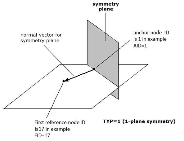
Figure 1. Pattern is activated and use TYP=1 (1-plane symmetry)
/DTPL/1
grpart 6 for topology optimization
### PATRN=1: active pattern
### TYP= 1: 1-plane symmetry
### AID=1: anchor node ID for variable pattern is 1
### FID=17: Node ID 17 used to define the direction of the first vector
#---1----|----2----|----3----|----4----|----5----|----6----|----7----|----8----|----9----|---10----|
#grpart_ID      TMIN    STRESS   MEMBSIZ     PATRN    PATREP      EXTR      MESH      DRAW
         6                                       1
#      TYP       AID                  XA                  YA                  ZA
         1         1
#                FID                  XF                  YF                  ZF
                  17
#     UCYC       SID                  XS                  YS                  ZS
#---1----|----2----|----3----|----4----|----5----|----6----|----7----|----8----|----9----|---10----|
Example (MMODIC)
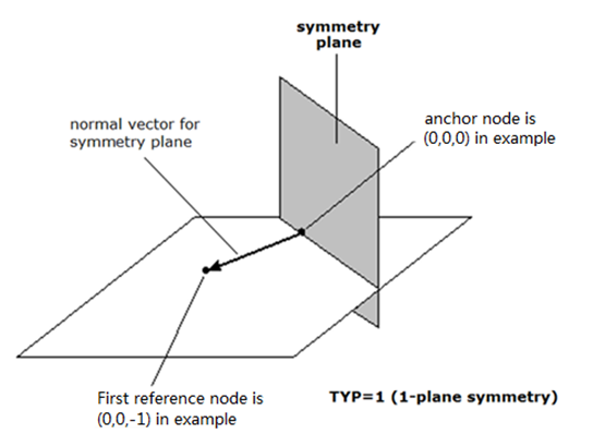
Figure 2.
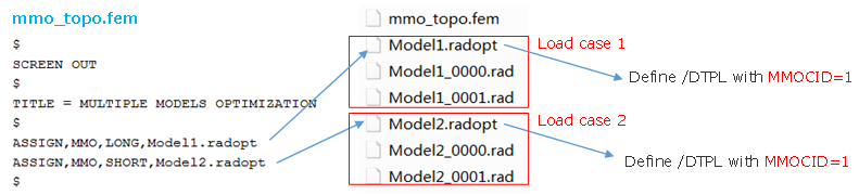
Figure 3.
#---1----|----2----|----3----|----4----|----5----|----6----|----7----|----8----|----9----|---10----|
/DTPL/1
grpart 1 for topology optimization
### MEMBSIZ=1: active member size control
### DRAW=1: active draw/casting direction constraint
### MMOCID=1: active Skew identifier flag for mapping the design domains in Multi-Model Optimization
### minimum diameter of members MINDIM=40 and maximum diameter of members MAXDIM=80
### TYP= 1: 1-plane symmetry
### Normal vector is from Anchor node (XA,YA,ZA) to First node (XF,YF,ZF)
### MCID=1: Skew identifier 1 used for mapping the design domains in Multi-Model Optimization
#---1----|----2----|----3----|----4----|----5----|----6----|----7----|----8----|----9----|---10----|
#grpart_ID      TMIN    STRESS   MEMBSIZ     PATRN    PATREP      EXTR      MESH      DRAW    MMOCID
         1                             1                                                 1         1
#             MINDIM              MAXDIM               MINGAP
                  40                  80
#      TYP       AID                  XA                  YA                  ZA
         1                             0                   0                   0
#                FID                  XF                  YF                  ZF
                                       0                   0                  -1
#     UCYC       SID                  XS                  YS
#     MCID
         1
#---1----|----2----|----3----|----4----|----5----|----6----|----7----|----8----|----9----|---10----|
Comments
- For PATRN=1
(active pattern), there are five pattern grouping options. This type of pattern grouping requires the anchor point and first point to be defined. A vector from the anchor point to the first point is normal to the plane of symmetry.
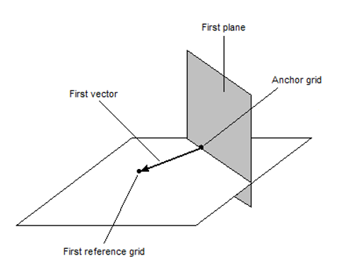
Figure 4. 1-plane symmetry (TYP = 1)This type of pattern grouping requires the anchor point, first point, and second point to be defined. A vector from the anchor point to the first point is normal to the first plane of symmetry. The second point is projected normally onto the first plane of symmetry. A vector from the anchor point to this projected point is normal to the second plane of symmetry.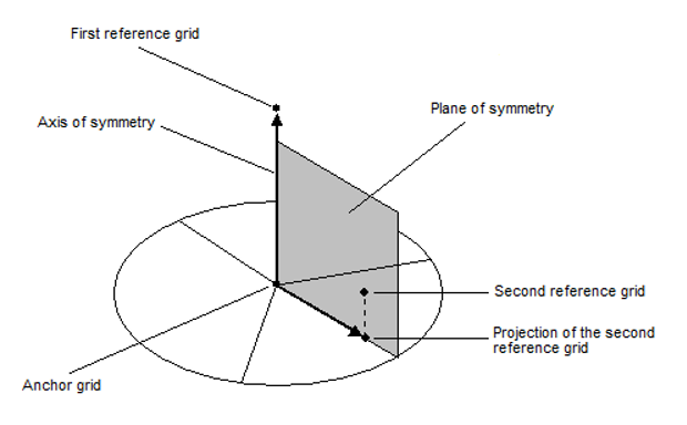
Figure 5. 2-plane symmetry (TYP = 2)This type of pattern grouping requires the anchor point, first point, and second point to be defined. A vector from the anchor point to the first point is normal to the first plane of symmetry. The second point is projected normally onto the first plane of symmetry. A vector from the anchor point to this projected point is normal to the second plane of symmetry. The third plane of symmetry is orthogonal to both the first and second planes of symmetry, passing through the anchor point.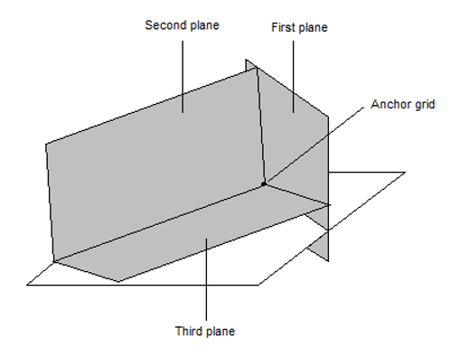
Figure 6. 3-plane symmetry (TYP = 3)This type of pattern grouping requires the anchor point, first point, and number of cyclical repetitions to be defined. A vector from the anchor point to the first point defines the axis of symmetry.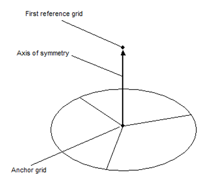
Figure 7. Cyclic (TYP = 10)This type of pattern grouping requires the anchor point, first point, second point, and number of cyclical repetitions to be defined. A vector from the anchor point to the first point defines the axis of symmetry. The anchor point, first point, and second point all lay on a plane of symmetry. A plane of symmetry lies at the center of each cyclical repetition.
Figure 8. Cyclic with symmetry (TYP = 11)For a more detailed description, refer to Pattern Grouping contained within the Topology Optimization Manufacturability section of the User Guide.
- PATREP =1,
read MAIN definitions for pattern repetition constraint.
PATREP =2, read SECOND definitions for pattern repetition constraint.
For a more detailed description, refer to Pattern Repetition.
- EXTRU =1,
read the extrusion constraint definition. There are two types of extrusion
constraints: ETYP=0 (non-twisted cross-section) and
ETYP =1 (twisted
cross-section).
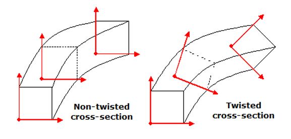
Figure 9.For a more detailed description, refer to Extrusion Constraints.
- DRAW =1,
read draw direction constraint definition. The type of draw direction that
could be used is single die (DTYP
=1).
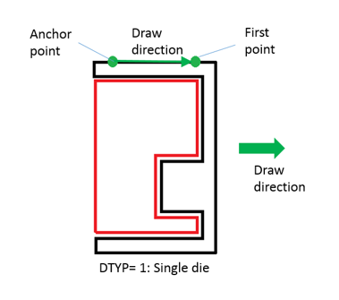
Figure 10.For a more detailed description, refer to Draw Direction Constraints.
- This entry is represented as an optimization design variable in HyperMesh and HyperCrash.