spot comparison
Spot comparison check configurations.
GUI Default Settings
- tolerance
- Distance between two spot welds less/equal to this tolerance are
considered matching. Distance more than this tolerance is reported as
positional difference.
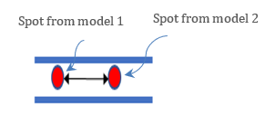
Figure 1. - slide-number
- The start number displayed on the top right corner of the PowerPoint slide.
- input-1
- Spot weld file 1.
- input-2
- Spot weld file 2 (same file cannot be selected).
- report
- Initial directory for report out path.
- action
- User action type to be executed.
- Check
- Only intersection check will be executed, no reports.
- Report
- Only Reports will be generated from the previous check.
- Both
- Check and Report generation will be executed in a sequence.
- extract-spot-cad-option
- CAD lines, points or solids are converted to spot weld file. A copy of
the spot weld file is stored in the input folder.
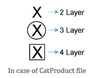
Figure 2. - extract-spot-method
- Logic to convert CAD to spot file.
- compname
- CAD names are used to recognize CAD spot data. These names are recognized via configuration file, name, connection and spot inputs.
- bbox
- Based on the location and surrounding parts, CAD is converted to spot weld file.
- position
- Position (Coordinates) difference between spot weld 1 and spot weld 2
will be reported if ON. Allowable positional difference is less than
tolerance value.
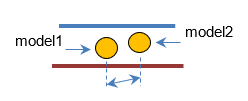
Figure 3. - part-id
- Part ID differences between spot weld 1 and spot weld 2 will be reported
if ON.
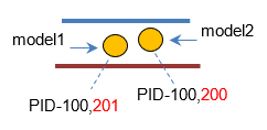
Figure 4. - layer
- #Layer, #Stack or #Link Components differences between spot weld 1 and
spot weld 2 will be reported if ON.
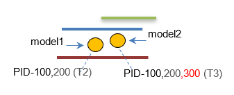
Figure 5.