Execution mode. Interactive mode will be slower than background
mode.
Default/Allowed: interactive or background
input
Initial director for CAD Input.
Default/Allowed: C:/temp
output
Initial director for results output.
Default/Allowed: C:/temp
Hole Detection
min-diameter
Minimum diameter for surface hole recognition. Holes below this diameter
will be ignored.
Default/Allowed: 1.0 to 10.0
max-diameter
Maximum diameter for surface hole recognition. Holes above this diameter
will be ignored.
Default/Allowed: 1.0 to 10.0
min-nodes
Minimum number of nodes to recognize FE hole. Holes with nodes less than
this number will be ignored.
Default/Allowed: 4 to 10
max-nodes
Maximum number of nodes to recognize FE hole. Holes with nodes greater
than this number will be ignored.
Default/Allowed: 30 to 50
adjacent-tolerance
Distance to judge duplicate holes for the same plate. If the Holes to
Holes distance is less than this value it is considered as a duplicate
hole.
Default/Allowed: 3.0 to 5.0
Free Hole
do-check
Turn OFF or ON the check.
Default/Allowed: ON or OFF
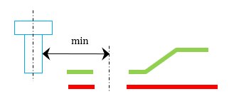
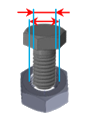
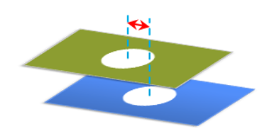
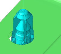
elem-adj-bbox-tolerance
Search tolerance for searching nearest bolts/nuts from the hole
center. Figure 1.
Default/Allowed: 10.0
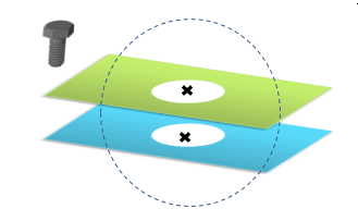
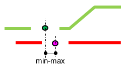
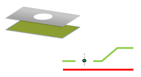
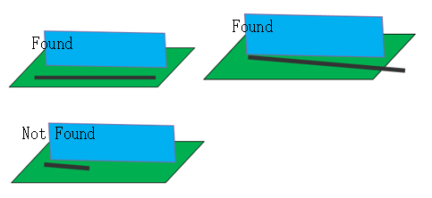
If there is no bolt, nut or screw nearby, the holes are considered as free holes. Figure 2.
freeboltnut
do-check
Turn OFF or ON the check.
Default/Allowed: ON or OFF
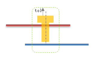
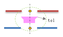
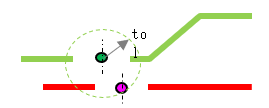
bolt-box-tolerance
Search tolerance for searching nearest plates from the bolt outer
surfaces. Figure 3.
Default/Allowed: 1.0 to 5.0
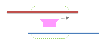
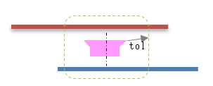
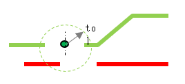
nut-box-tolerance
Search tolerance for searching nearest plates from the nut outer
surface. Figure 4.
Default/Allowed: 5.0 to 10.0
allowed-plate-comps
These named parts will not be considered as plates.
Default/Allowed: string names of special parts
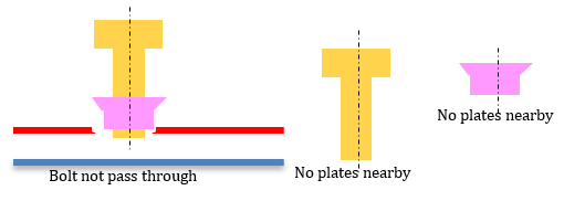
Bolt or Nut CAD data that are not passing through the plates or floating in the space
without the plates are found. Figure 5.
bolthole-mismatch
do-check
Turn OFF or ON the check.
Default/Allowed: ON or OFF
input-type
Continuous CAD lines or CAD solids.
Default/Allowed: lines or solids
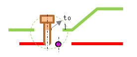
centernode-search-tolerance
Search tolerance for searching holes from bolt CAD surface. Figure 6.
Default/Allowed: 1.0 to 2.0
elem-adj-bbox-tolerance
Tolerance for searching nearest plates from the bolt outer surface. Figure 7.
Default/Allowed: 5.0 to 10.0
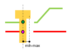
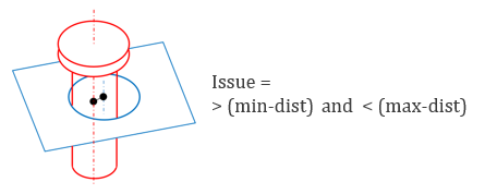
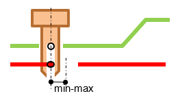
min-dist
Allowable mismatch distance between bolt axis and hole axis. Figure 8.
Default/Allowed: 0.1 to 1.0
max-dist
Maximum search distance between bolt axis and the hole axis.
Default/Allowed: 5.0 to 10.0
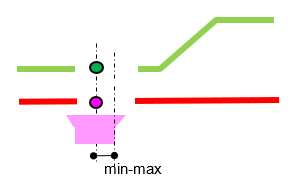
Mismatch issues are found if the mismatch is between min-dist to max-dist value. Figure 9.
nuthole-mismatch
do-check
Turn OFF or ON the check.
Default/Allowed: ON or OFF
input-type
Continuous CAD lines or CAD solids.
Default/Allowed: lines or solids
centernode-search-tolerance
Search tolerance for searching holes from bolt/nut CAD surface. Figure 10.
Default/Allowed: 1.0 to 2.0
elem-adj-bbox-tolerance
Tolerance for searching nearest plates from the nut outer surface. Figure 11.
Default/Allowed: 5.0 to 10.0
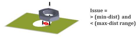
min-dist
Allowable mismatch distance between nut axis and hole axis. If the
mismatch is less than this value issues will not be reported. Figure 12.
Default/Allowed: 0.1 to 1.0
max-dist
Maximum search distance between nut axis and the hole axis. If the
mismatch is greater than this value issues will not be reported.
Default/Allowed: 5.0 to 10.0
Issues are found if the mismatch distance is between min-dist to max-dist range. Figure 13.
boltnut-mismatch
do-check
Turn OFF or ON the check.
Default/Allowed: ON or OFF
elem-adj-bbox-tolerance
Tolerance for searching nearest plates from the nut outer surface. Figure 14.
Default/Allowed: 5.0 to 10.0
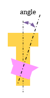
threshold-angle
Allowable angle between center axis of bolt and the nut. More than this
angle, the check will be ignored for that pair of connection parts. Figure 15.
Default/Allowed: 10.0 to 30 deg
min-dist
Allowable mismatch distance between nut axis and hole axis. If the
mismatch is less than this value issues will not be reported. Figure 16.
Default/Allowed: 0.1 to 1.0
max-dist
Maximum search distance between nut axis and the hole axis. If the
mismatch is greater than this value, issues will not be reported.
Default/Allowed: 5.0 to 10.0
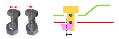
Bolt-nut mismatch issues will be reported if the Bolt and Nut sizes are not within
min-dist and max-dist range. Figure 17.
boltnutsize-mismatch
do-check
Turn OFF or ON the check.
Default/Allowed: ON or OFF
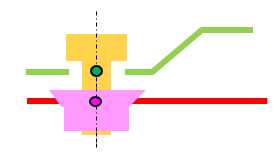
elem-adj-bbox-tolerance
Tolerance for searching nearest bolt, plates from the nut outer
surface. Figure 18.
Default/Allowed: 5.0 to 10.0
min-dist
Allowable mismatch distance between nut axis and hole axis. If the
mismatch is less than this value issues will not be reported. Figure 19.
Default/Allowed: 0.1 to 1.0
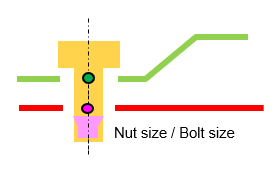
min-nut-tol-bolt-ratio
Allowable minimum ratio between bolt and nut size. If the ratio is less
than this value the issue is reported. Figure 20.
Default/Allowed: 0.8 to 0.9
max-nut-tol-bolt-ratio
Allowable maximum ratio between bolt and the nut size. If the ratio is
greater than this value the issue is reported. Figure 21.
Default/Allowed: 1.1 to 1.3
Issues will be reported if the Bolt size and Nut size are not within the range of
min-nut-tol-bolt-ratio and the max-nut-tol-bolt-ratio. Figure 22.
holes-mismatch
do-check
Turn OFF or ON the check.
Default/Allowed: ON or OFF
min-dist
Allowable mismatch distance between nut axis and hole axis. If the
mismatch is less than this value the issues will not be reported. Figure 23.
Default/Allowed: 0.1 to 1.0
max-dist
Maximum search distance between hole center node axis.
Default/Allowed: 5.0 to 10.0
centernode-search-tolerance
Tolerance for searching nearest plates from the hole center. Figure 24.
Default/Allowed: 1.0 to 2.0
elem-adj-bbox-tolerance
Tolerance for searching nearest plates from the hole center. Figure 25.
Default/Allowed: 5.0 to 10.0
Issues will be reported if the center axis distance between two holes are not with
the min-dist and max-dist. Figure 26.
holespair-mismatch
do-check
Turn OFF or ON the check.
Default/Allowed: ON or OFF
elem-adj-bbox-tolerance
Tolerance for searching nearest plates from the hole center. Figure 27.
Default/Allowed: 5.0 to 10.0
centernode-search-tolerance
Tolerance for searching nearest plates from the hole center. Figure 28.
Default/Allowed: 1.0 to 2.0
Holes not found in the nearest plates are reported as an issue nearest plates. Plate
holes are searched with centernode-search-tolerance tolerance. Figure 29.
Clip-mismatch
do-check
Turn OFF or ON the check.
Default/Allowed: ON or OFF
input-type
Continuous CAD lines or CAD solids.
Default/Allowed: lines or solids
centernode-search-tolerance
Search tolerance from center clip to holes center. Figure 30.
Default/Allowed: 1.0 to 2.0
min-dist
Allowable mismatch distance between clip axis and hole axis. Figure 31.
Default/Allowed: 0.5 to 1.0
max-dist
Maximum distance between clip axis and the hole axis. Greater than this
value the clip parts are ignored in the check.
Default/Allowed: 5.0 to 15.0
Issues will be reported if the center axis of clip data and the center axis of the
hole node is greater than the min-dist and less than max-dist. Figure 32.
Arc/Seam/Adhesive/Seal/Hemming -mismatch
do-check
Turn OFF or ON the check.
Default/Allowed: ON or OFF
input-type
Continuous CAD lines or CAD solids.
Default/Allowed: lines or solids
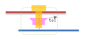
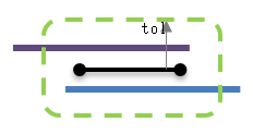
elem-adj-bbox-tolerance (tol)
Search tolerance for finding the nearest weldable plates. If less than
two parts are found the issue is reported. Figure 33.
Default/Allowed: 10.0
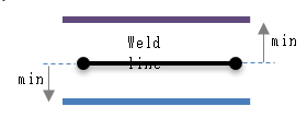
min-dist
Minimum distance between arc weld to the nearest parts. If less than two
parts are found the issue is reported.
Default/Allowed: 0.1 to 5.0
max-dist
Maximum distance between weld lines to the nearest parts.
Default/Allowed: 5.0 to 10.0
Finds shape mismatch between the weld lines against the plates with the given min and
max distance.
The mismatches are measured from the end points of the line. Figure 34.