Restriction: Available in Abaqus, Nastran, and OptiStruct.
Use the RBE3 Load Transfer realization to create MPCs using RBE3 elements between the
nodes of shell-shell, shell-solid, or solid-solid groups by using spot connectors.
Solid-Solid
Figure 1.
Shell-Shell (Face to Face)
Figure 2.
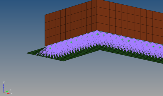
Shell-Shell (Edge to Face)
For successful realization of these connectors, the non-normal projection option
needs to be active. Otherwise the projection onto an edge does not work. Figure 3.
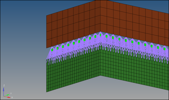
Shell-Shell (Edge to Edge)
For successful realization of these connectors, the non-normal projection option
needs to be active. Otherwise the projection onto an edge does not work. Figure 4.
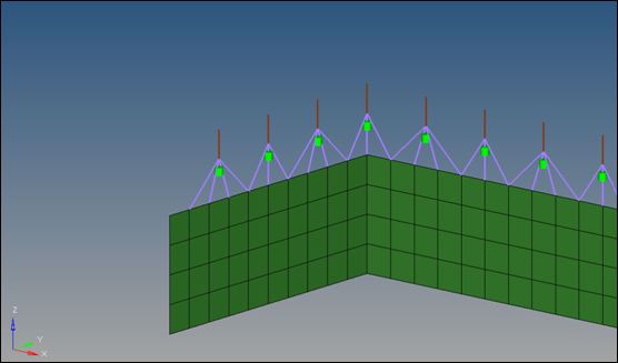
Shell-Beam
This situation is a very specific and requires some preparation to be successful,
since the projection onto 1D elements is not supported. In this situation, you need
to enable the non-normal projection checkbox for the
projection onto the edge. In addition, the node of the 1D element needs to be
defined directly as a link. Normally this is done during connector creation by
activating add node location as link.
Note: This option is only available for nodes
as connector location, and only if the center definition is set to use connector
position for center.
Figure 5. Shell-Beam
Center definition options include:
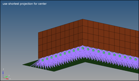
use shortest projection for center
The closest node becomes the center of the RBE3 element.
During the realization, based on the connector position and the
tolerance, the closest links are determined up to the number of required
layers (num layer). All other link candidates are not taken into account
for the next step. The closest node is also determined and becomes the
center of the RBE3 element. Based on this center position, all nodes
within the given tolerance (distance center to node) and belonging to
the remained links are attached to the RBE3 element.
Note: If the
connector has been created with the option add location node as
link, the use shortest projection for center option is ignored and
the linked node becomes the center of the RBE3 element.
Figure 6. Use Shortest Projection For Center
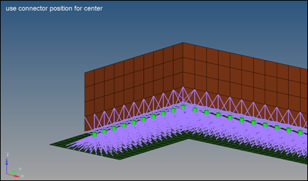
use connector position for center
The exact position of the connector becomes the center of the RBE3
element. Figure 7. Use Connector Position For Center
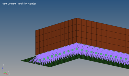
use coarse mesh for center
During the realization, based on the connector position and tolerance,
the closest links are determined up to the number of required layers
(num layer). All other link candidates are not taken into account for
the next step.
From the remaining links, the one with the coarsest mesh is identified
and a node on this mesh (close to the perpendicular connector
projection) becomes the center of the RBE3 element. Based on this center
position, all nodes within the given tolerance (distance center to node)
and belonging to the remaining links are attached to the RBE3
element.
Note: If the connector has been created with the add
location node as link option, the use shortest projection for center
option is ignored and the linked node becomes the center of the RBE3
element. Figure 8. Use Coarse Mesh For Center