Restriction: Available in Abaqus, Nastran, and OptiStruct.
Creates a hexa element with RBE3 (Nastran/OptiStruct) or DCOUP3D (Abaqus)
elements projecting and connecting to the surrounding shell elements. This realization
uses the shell thickness to calculate the hexa offset from the shell elements. In the
case where the model is a 3T connection, the acm (equivalenced-(T1+T2)/2) realization
will join the hexa elements.
For Nastran and OptiStruct, this
realization uses the prop_nastran_acm.tcl property script. For
Abaqus, it uses
prop_abaqus_acm.tcl. Figure 1.
ACM Realization Options
Option
Action
thickness
Select a thickness
option used for dimensioning and positioning hexas.
shell gap
Project the hexa spot to touch the shell
elements.
The position is independent from any thickness.
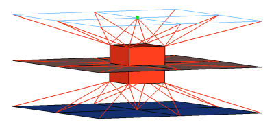
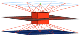
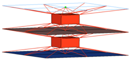
equival. (T1+T2)/2
Create hexa elements with RBE3 elements projecting
and connecting to the surrounding shell
elements.
This realization uses the shell thickness to
calculate the hexa offset from the shell elements.
In the case where the model is a 3T connection, the
acm (equivalenced-(T1+T2)/2) realization will join
the hexa elements. Figure 2.
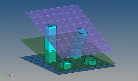
detached (T1+T2)/2
Create hexa elements with RBE3 elements projecting
and connecting to the surrounding shellstr
elements.
This realization uses the shell thickness to
calculate the hexa offset from the shell elements.
In the case where the model is a 3T connection, the
acm (detached-(T1+T2)/2) realization will not join
the hexa elements. Figure 3.
mid thickness
Calculate the hexa spot size (thickness) as the air
gap between the two connected parts. If there is no
gap, or even a penetration, the hexa spot size will
always be modeled with 1.0.
const thickness
Specify the hexa spot size (thickness).
maintain gaps
Calculate the hexa spot size (thickness) as the gap
distance reduced by two times the specified value
for maintain gaps.
The position is independent from any thickness.
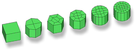
num hexas
Create a hexa cluster
with 1, 4, 8, 12, 16 or 32 hexas, which are arranged in a
predefined pattern. Figure 4.
Note: Available for all ACM realization
types.
coats
Define the number of
hexa elements required along the thickness. Multiple solid coats
are supported.
orthogonal
faces
Force the creation of
perfectly orthogonally-shaped hexas. Figure 5. . The two leftmost realizations were performed with the
orthogonal faces option enabled.
Note: Available for any kind of ACM weld, if num hexas is
set to 1.