acm (shell gap contact + coating)
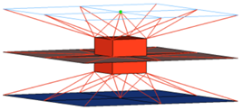
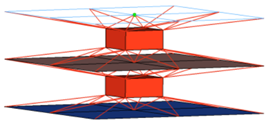
This realization creates hexa clusters between shell components. Contacts get defined between the shell components and the appropriate hexa nodes. A heat affected zone for the shells from ultra high strength steel material is also created.
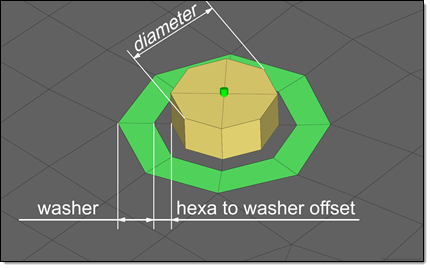
Figure 1. Heat Affected Zone Dimensions
This realization uses the prop_rad_acm_shellgapcoating.tcl property script.
Organization and Definition of ACM (Shell Gap Contact and Coating)
- For each connected link the contact /inter/TYPE2/ gets created and is named
TYPE2_CONTACT_PID_<link ID>. The following sets are created and
referenced.
- MAINPART_SET_PID_<link ID>: In this set, which is referenced as the main by the above mentioned contact, the link entities like the component get organized.
- SECONDARYNODE_SET_PID_<link ID>: In this set, which is referenced as the secondary by the above mentioned contact, the hexa nodes projecting onto the master entities get organized.
- For each link combination the hexa clusters are organized into separate
components and named RAD_SOLID_SPOTWELD_PID_<link1 ID>_<link2 ID>. All
components are assigned the following material and property:
- RAD_SOLID_SPOTWELD_DEFAULT_MAT. This material is defined as /MAT/LAW59/.
- RAD_SOLID_SPOTWELD_DEFAULT_PROP. This property is defined as
/PROP/CONNECT/.
The default values are read from uhss_washersolid_matprop.rad in the installation.
- The heat affected zone elements (washer) are organized into one separate
component for each link from the ultra high strength steel material and
named RAD_WASHER_PID_<link ID>. All components are assigned the following
material and property:
- RAD_WASHER_MAT. This material is defined as /MAT/PLAS_JOHNS/.
- RAD_WASHER_PROP. This property is defined as
/PROP/SHELL/.
The material and property values are read from uhss_washersolid_matprop.rad in the installation.
Defining Materials for Heat Affected Zone Treatment
You must specify which materials are considered as ultra high strength materials. When defining an acm (shell gap contact and coating) connector, the UHSS Material Option can be selected for individual connectors using the Connector Entity Editor.
- From current model
- Select an existing material from the current model.
- From search file (default)
- For acm (shell gap contact and coating) realizations, the material
search file name is materialsnippets.txt. HyperMesh searches for this file in the following
locations and in the following order:
- Installation: [hm_scripts_dir]/connectors/materialsnippets.txt
- User directory: [USER_HOME]/materialsnippets.txt
- HyperWorks Configuration Path folder: [HW_CONFIG_PATH]/materialsnippets.txt
- Current working folder:
[CURRENTWORKINGDIR]/materialsnippets.txtv
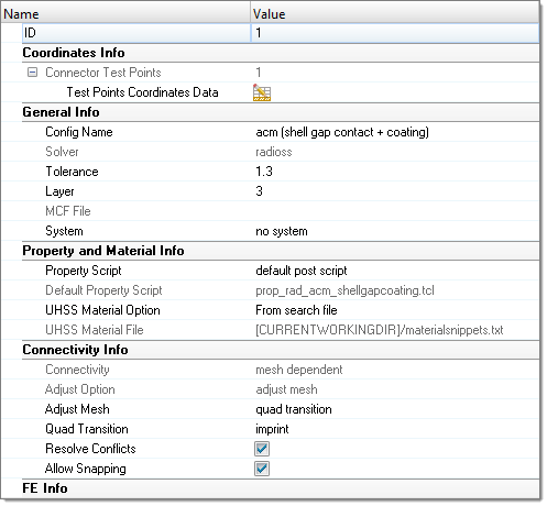
Figure 2. From Search File
- From connector metadata
- Once a connector is realized with the UHSS Material Option “From search
file”, the folder name is written as metadata to the connector in a
relative manner to allow the exact same rerealization in a different
work environment as long as the same
materialsnippets.txt files are saved in
according folders.
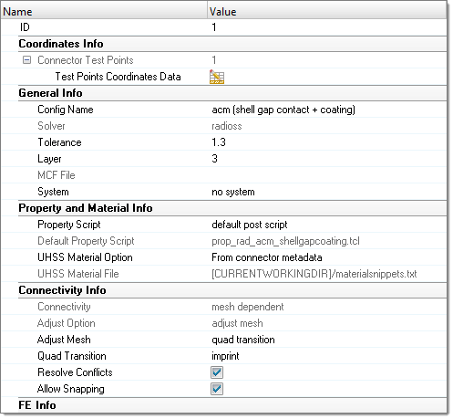
Figure 3. From Connector Metadata
ACM Realization Options
| Option | Action |
|---|---|
| thickness | Select a thickness
option used for dimensioning and positioning hexas.
|
| num hexas | Create a hexa cluster
with 1, 4, 8, 12, 16 or 32 hexas, which are arranged in a
predefined pattern.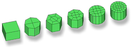 Figure 6. Note: Available for all ACM realization
types.
|
| coats | Define the number of hexa elements required along the thickness. Multiple solid coats are supported. |
| orthogonal faces | Force the creation of
perfectly orthogonally-shaped hexas.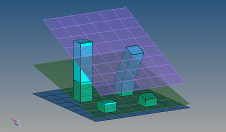 Figure 7. . The two leftmost realizations were performed with the orthogonal faces option enabled. Note: Available for any kind of ACM weld, if num hexas is
set to 1.
|