Create and Realize Connectors
Use the tools in the Create tool set to create connectors, assign controls, and realize.
-
On the guide bar, click
 to define connector options.
-
Use the options in the microdialog to further define
the connector.
The following options are available for all entity types and tools.
Option Description Move/Morph (  )
)Relocate sections or the whole connector to a different position Link Edit (  )
)Opens a dialogue that allows you to adjust the link detection logic. Show/Hide Projections (  )
)Show and hide the pre-projections that indicate where the connector will connect to. Other options are dependent on the entity type and selected tool.Option Description Trim (  )
)Split the connector at a selected position. Available for node list, line, element, and surface selection.
Partition (  )
)Partition the seam connector if any part of that connector does not have projections. Only available for the Line tool.
Pitch and Density - Pitch (
 )
) - Adjust the number of significant points along the connector line by given spacing.
- Density (
 )
) - Adjust the number of significant points along the connector line by a number.
Available for node list and line selection in the Point and Line tools.
Line Interpolation - Straight line (
 )
) - A straight interpolation line is created between the
selected nodes.
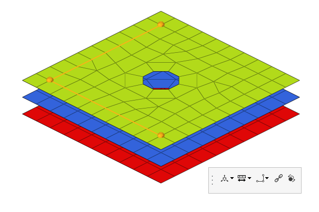
Figure 1. - Interpolated line (
 )
) - A smoothed interpolation line is created between the
selected nodes.
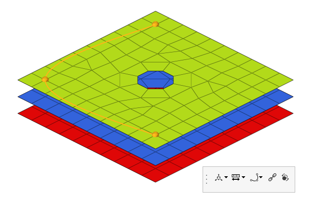
Figure 2.
Available for node list selection in the Point and Line tools.
Line Creation - None (
 )
) - Leave the line selections separate.
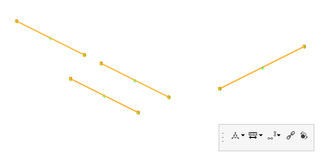
Figure 3. - Combine Smooth (
 )
) - Combine selected lines with an interpolated line.
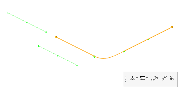
Figure 4. - Combine Straight (
 )
) - Combine selected lines with a straight line.
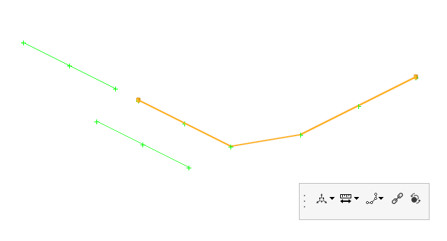
Figure 5. - Mid Line (
 )
) - Generate a midline between selected lines.
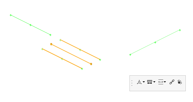
Figure 6.
Only available for line selection.
Remesh (  )
)Remesh the connector surface. 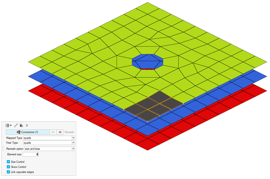
Figure 7.
Available for any selection type in the Area tool.
- Pitch (
-
On the guide bar, click one of the following:
 - Save changes and stay in the tool
 - Save changes and close the tool
 - Exit the tool without saving changes