Rapidly change the shape of the FE mesh without severely sacrificing the mesh quality and create, edit, and apply
shapes for subsequent design optimization studies.
The Design Space environment is dedicated to topology optimization model build and setup. It facilitates rapid model creation by generating
the voxel design space for a number of different use cases.
Many essential utility tools using HyperWorks-Tcl have been developed over the years to support Aerospace customers. A few tools have been collected and upgraded to
be compatible with this release.
Open animation files, measure various distances and angles between entities, and use the Results Browser to view the model structure and find, display, and edit entities.
Create and edit user-defined data type expressions, derived load cases, and systems. You can also plot a forming limit
diagram, generate streamlines, track entities during animation, and create and import/export sets of entities.
The list of available operators is controlled by the template file selected when loading a model and result, and it can
be modified by adding or removing <using /> statements in the template.
A result manipulation library that enables user-defined data types to be added to a result, and transitions complex data
manipulation tasks from HyperView to a reusable, modifiable set of libraries that focus solely on result processing tasks.
Use the FLD tool a plot a Forming Limit Diagram (FLD) based on a material Forming Limit Curve (FLC) and the major and
minor strain output results of a forming simulation.
Query entities, create or edit free body diagrams, construct multiple curves and plots from a single result file, and
create and plot stress linearization.
A result manipulation library that enables user-defined data types to be added to a result, and transitions complex data
manipulation tasks from HyperView to a reusable, modifiable set of libraries that focus solely on result processing tasks.
Create and edit user-defined data type expressions, derived load cases, and systems. You can also plot a forming limit
diagram, generate streamlines, track entities during animation, and create and import/export sets of entities.
The Spatial (Beta) library contains functions that deal with minimum distance and
result mapping.
The operators in the spatial library are available
only through XML, and are not available via the Expression Builder.
The minimum distance and
value mapping functionality has been updated since it was first introduced, however it is
still in beta form for testing purposes. These operators may change before they are
finalized.
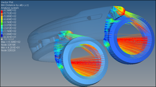
Calculation of minimum distance from two node sets (the tire) to an element
set (the bumper fascia) using the NSMinDisance operator with the display
option set to “byall”:
Figure 1.
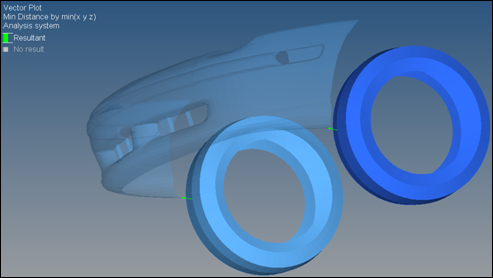
The same operation with the display option set to “bymin”
shows a single vector from each “from” patch to the element set:
Figure 2.
The result is a vector that can be plotted directly or contoured.
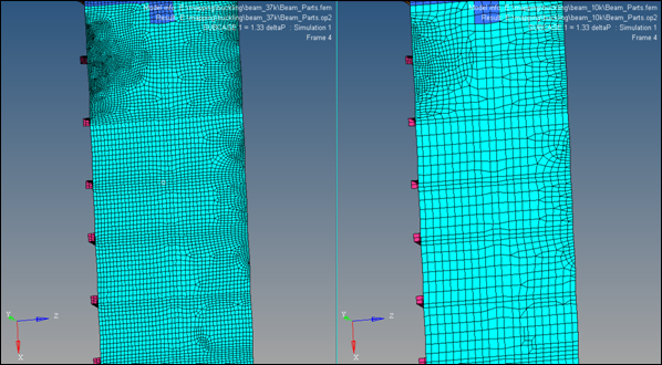
Mapping
of values from one model/result to another, can also be performed using
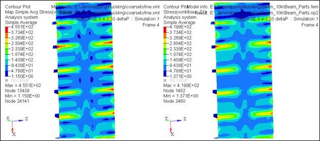
ValueMapToNode. The image below shows both a coarse and fine model:
Figure 3.
The model on the left is fine (~37K elements), and shows values mapped to from
the coarse model on the right (~10K elements):
Figure 4.
NSMinDistance
Calculates the minimum distance from nodes to elements.
ValueMapToNode
Maps values from a source model to nodes on a destination model.