Tire Subroutine Arguments
| Argument | Type | Description | |||||||||||||||||||||||||||||||||||||||||||||||||||||||||||||||||||||||||||||||||||||||||||||||||||||||||||||||||||||||||||||||||||||||||||||||||||||||||||||||||||||||||||||||||||||||||||||||||||||||||||||||||||||||||||||||||||||||||||||||||||||||||||||||||||||||||||||||||||||||||||||||||||||||||||||||||||||||||||||||||
|---|---|---|---|---|---|---|---|---|---|---|---|---|---|---|---|---|---|---|---|---|---|---|---|---|---|---|---|---|---|---|---|---|---|---|---|---|---|---|---|---|---|---|---|---|---|---|---|---|---|---|---|---|---|---|---|---|---|---|---|---|---|---|---|---|---|---|---|---|---|---|---|---|---|---|---|---|---|---|---|---|---|---|---|---|---|---|---|---|---|---|---|---|---|---|---|---|---|---|---|---|---|---|---|---|---|---|---|---|---|---|---|---|---|---|---|---|---|---|---|---|---|---|---|---|---|---|---|---|---|---|---|---|---|---|---|---|---|---|---|---|---|---|---|---|---|---|---|---|---|---|---|---|---|---|---|---|---|---|---|---|---|---|---|---|---|---|---|---|---|---|---|---|---|---|---|---|---|---|---|---|---|---|---|---|---|---|---|---|---|---|---|---|---|---|---|---|---|---|---|---|---|---|---|---|---|---|---|---|---|---|---|---|---|---|---|---|---|---|---|---|---|---|---|---|---|---|---|---|---|---|---|---|---|---|---|---|---|---|---|---|---|---|---|---|---|---|---|---|---|---|---|---|---|---|---|---|---|---|---|---|---|---|---|---|---|---|---|---|---|---|---|---|---|---|---|---|---|---|---|---|---|---|---|---|---|---|---|---|---|---|---|---|---|---|---|---|---|---|---|---|---|---|---|---|---|---|---|---|---|---|---|---|---|---|---|---|---|---|---|---|---|---|---|
| NDEV | Input | Integer | NDEV must specify the logical output device for error messages. USRMES and ERRMES can be used in place of writing to NDEV device. | ||||||||||||||||||||||||||||||||||||||||||||||||||||||||||||||||||||||||||||||||||||||||||||||||||||||||||||||||||||||||||||||||||||||||||||||||||||||||||||||||||||||||||||||||||||||||||||||||||||||||||||||||||||||||||||||||||||||||||||||||||||||||||||||||||||||||||||||||||||||||||||||||||||||||||||||||||||||||||||||||
| ISWTCH | Input | Integer | ISWTCH is a copy of USE_MODE which a variable in Tire property file. USE_MODE
is a user controlled variable to select among the different operating modes of
tire. If a user has different kinds of tire model than in JOBFLG = 11 the User Tire Interface will send the ISWTCH as a input to the tire subroutine and at this JOBFLG specific algorithm is selected depending on the value of the ISWTCH. Example:
If
USE_MODE = 121 than it means that the ISWTCH value at JOBFLG = 11 is 121 and
this value specifies
In a similar manner, ISWTCH can be defined so that by addition of digits which represents the corresponding evaluation schemes can be represented by this parameter. |
||||||||||||||||||||||||||||||||||||||||||||||||||||||||||||||||||||||||||||||||||||||||||||||||||||||||||||||||||||||||||||||||||||||||||||||||||||||||||||||||||||||||||||||||||||||||||||||||||||||||||||||||||||||||||||||||||||||||||||||||||||||||||||||||||||||||||||||||||||||||||||||||||||||||||||||||||||||||||||||||
| JOBFLG | Input | Integer | The User Tire Interface calls the User Tire model several times during the
simulation with different JOBFLG. The JOBFLG variable decides the execution model
(initialization, reading tire property file, initial condition) of TYRE. The User
Tire Interface expects some variables to be updated according to the JOBFLG value.
The JOBFLG is called in following order: JOBFLG = 1 initialization mode This mode is for initialization of the tire, it will be called once for each tire. After this call the User Tire Interface expects the tire model to return the maximum array size for the arrays to store the tire properties, road properties, state variables and output variables. Outputs: NTYPAR NDEQVR, NVARS, NWORK, NIWORK, NROPAR JOBFLG = 2 reading tire and road property files In this mode tire model reads the tire and road property files and stores the parameters in TYPARR, ROPAR and WRKARR array. Inputs: NCHTDS, CHTDST, NCHRDS, CHRDST, ISWTCH, IDTYRE Output: TYPARR, ROPAR, WRKARR JOBFLG = 11, actual array size Depending on the ISWTCH or depending on the parameters in tire property file the number of differential equations can vary which in turn changes the number of states therefore User Tire Interface needs to be updated about the size of the state and work arrays. Input: ISWTCH Output: NTYPAR, NDEQVR, NVARS, NWORK, NIWORK JOBFLG = 6, initial conditions In this call depending on the kinematic inputs (position, velocity, orientation) of the wheel center, the initial conditions for state variables can be calculated. Inputs: ISWTCH, TIME, DIS, TRAMAT, ANGTWC, VEL, OMEGA, OMEGAR, DEQVAR, TYPARR, ROPAR Output: DEQINI JOBFLG = 0, normal call In this call tire model calculates the force and moments on tire. Inputs: ISWTCH, TIME, DIS, TRAMAT, ANGTWC, VEL, OMEGA, OMEGAR, DEQVAR, TYPARR, ROPAR Outputs: FORCE, TORQUE, DEQDER, VARINF, WRKARR, and IWRKAR JOBFLG = 99, final call This is the final call to tire model and is used to inform tire model to free allocated memory, etc. |
||||||||||||||||||||||||||||||||||||||||||||||||||||||||||||||||||||||||||||||||||||||||||||||||||||||||||||||||||||||||||||||||||||||||||||||||||||||||||||||||||||||||||||||||||||||||||||||||||||||||||||||||||||||||||||||||||||||||||||||||||||||||||||||||||||||||||||||||||||||||||||||||||||||||||||||||||||||||||||||||
| IDTYRE | Input | Integer | Specifies the tire ID. | ||||||||||||||||||||||||||||||||||||||||||||||||||||||||||||||||||||||||||||||||||||||||||||||||||||||||||||||||||||||||||||||||||||||||||||||||||||||||||||||||||||||||||||||||||||||||||||||||||||||||||||||||||||||||||||||||||||||||||||||||||||||||||||||||||||||||||||||||||||||||||||||||||||||||||||||||||||||||||||||||
| TIME | Input | Real | Current simulation time. | ||||||||||||||||||||||||||||||||||||||||||||||||||||||||||||||||||||||||||||||||||||||||||||||||||||||||||||||||||||||||||||||||||||||||||||||||||||||||||||||||||||||||||||||||||||||||||||||||||||||||||||||||||||||||||||||||||||||||||||||||||||||||||||||||||||||||||||||||||||||||||||||||||||||||||||||||||||||||||||||||
| DIS | Input | Real array (3) | Specifies the x, y, z coordinates of the wheel carrier at the wheel center with respect to the earth-fixed axis system expressed in the earth-fixed axis system. Earth fixed axis system and Road reference marker coordinate system are same. | ||||||||||||||||||||||||||||||||||||||||||||||||||||||||||||||||||||||||||||||||||||||||||||||||||||||||||||||||||||||||||||||||||||||||||||||||||||||||||||||||||||||||||||||||||||||||||||||||||||||||||||||||||||||||||||||||||||||||||||||||||||||||||||||||||||||||||||||||||||||||||||||||||||||||||||||||||||||||||||||||
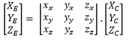
| TRAMAT | Input | Real array (3,3) | Specifies the transformation matrix to transform data from the wheel Carrier
coordinate system to the earth-fixed axis system.
|
||||||||||||||||||||||||||||||||||||||||||||||||||||||||||||||||||||||||||||||||||||||||||||||||||||||||||||||||||||||||||||||||||||||||||||||||||||||||||||||||||||||||||||||||||||||||||||||||||||||||||||||||||||||||||||||||||||||||||||||||||||||||||||||||||||||||||||||||||||||||||||||||||||||||||||||||||||||||||||||||
| ANGTWC | Input | Real | Specifies the rotation angle of the rim w.r.t. the wheel carrier (used for positioning /triggering of non-uniformities of the tire). | ||||||||||||||||||||||||||||||||||||||||||||||||||||||||||||||||||||||||||||||||||||||||||||||||||||||||||||||||||||||||||||||||||||||||||||||||||||||||||||||||||||||||||||||||||||||||||||||||||||||||||||||||||||||||||||||||||||||||||||||||||||||||||||||||||||||||||||||||||||||||||||||||||||||||||||||||||||||||||||||||
| VEL | Input | Real array (3) | Specifies the translational velocities of the wheel career at the wheel center with respect to the earth-fixed axis system expressed in the C-frame (defined in the TYDEX - Format). | ||||||||||||||||||||||||||||||||||||||||||||||||||||||||||||||||||||||||||||||||||||||||||||||||||||||||||||||||||||||||||||||||||||||||||||||||||||||||||||||||||||||||||||||||||||||||||||||||||||||||||||||||||||||||||||||||||||||||||||||||||||||||||||||||||||||||||||||||||||||||||||||||||||||||||||||||||||||||||||||||
| OMEGA | Input | Real array (3) | Specifies the angular velocities of the wheel carrier with respect to the earth-fixed axis system expressed in the wheel carrier (C-frame) axis system. | ||||||||||||||||||||||||||||||||||||||||||||||||||||||||||||||||||||||||||||||||||||||||||||||||||||||||||||||||||||||||||||||||||||||||||||||||||||||||||||||||||||||||||||||||||||||||||||||||||||||||||||||||||||||||||||||||||||||||||||||||||||||||||||||||||||||||||||||||||||||||||||||||||||||||||||||||||||||||||||||||
| OMEGAR | Input | Real | Specifies the rotation speed of the rim with respect to the wheel carrier. | ||||||||||||||||||||||||||||||||||||||||||||||||||||||||||||||||||||||||||||||||||||||||||||||||||||||||||||||||||||||||||||||||||||||||||||||||||||||||||||||||||||||||||||||||||||||||||||||||||||||||||||||||||||||||||||||||||||||||||||||||||||||||||||||||||||||||||||||||||||||||||||||||||||||||||||||||||||||||||||||||
| NDEQVR | Input | Integer | Specifies the dimension of the DEQVAR array. It is the number of states required by tire model. | ||||||||||||||||||||||||||||||||||||||||||||||||||||||||||||||||||||||||||||||||||||||||||||||||||||||||||||||||||||||||||||||||||||||||||||||||||||||||||||||||||||||||||||||||||||||||||||||||||||||||||||||||||||||||||||||||||||||||||||||||||||||||||||||||||||||||||||||||||||||||||||||||||||||||||||||||||||||||||||||||
| DEQVAR | Input | Real array (NDEQVR) | DEAQVAR contains the integrated values of the DEQDER. The initial values are given by DEQINI. | ||||||||||||||||||||||||||||||||||||||||||||||||||||||||||||||||||||||||||||||||||||||||||||||||||||||||||||||||||||||||||||||||||||||||||||||||||||||||||||||||||||||||||||||||||||||||||||||||||||||||||||||||||||||||||||||||||||||||||||||||||||||||||||||||||||||||||||||||||||||||||||||||||||||||||||||||||||||||||||||||
| NTYPAR | Input | Integer | Specifies the dimension of the TYPARR array. If NTYPAR is equal to zero than TYPARR contains no available values. | ||||||||||||||||||||||||||||||||||||||||||||||||||||||||||||||||||||||||||||||||||||||||||||||||||||||||||||||||||||||||||||||||||||||||||||||||||||||||||||||||||||||||||||||||||||||||||||||||||||||||||||||||||||||||||||||||||||||||||||||||||||||||||||||||||||||||||||||||||||||||||||||||||||||||||||||||||||||||||||||||
| TYPARR | Input | Real array (NTYPAR) | It contains the parameters of the current tire model. If TYPARR is not available than NTYPAR must be 0 and in this case tire parameters can be read from a data file specified in CHTDST. | ||||||||||||||||||||||||||||||||||||||||||||||||||||||||||||||||||||||||||||||||||||||||||||||||||||||||||||||||||||||||||||||||||||||||||||||||||||||||||||||||||||||||||||||||||||||||||||||||||||||||||||||||||||||||||||||||||||||||||||||||||||||||||||||||||||||||||||||||||||||||||||||||||||||||||||||||||||||||||||||||
| NCHTDS | Input | Integer | Specifies the dimension of CHTDST array. If NCHTDS is 0 than CHTDST contains no file name and in this case the simulation will be terminated as tire property file is used to inform User Tire Interface about the Tire subroutine name and the library name. | ||||||||||||||||||||||||||||||||||||||||||||||||||||||||||||||||||||||||||||||||||||||||||||||||||||||||||||||||||||||||||||||||||||||||||||||||||||||||||||||||||||||||||||||||||||||||||||||||||||||||||||||||||||||||||||||||||||||||||||||||||||||||||||||||||||||||||||||||||||||||||||||||||||||||||||||||||||||||||||||||
| CHTDST | Input | Character array (NCHTDS) |
It contains the tire property file name which has tire parameters stored in it. | ||||||||||||||||||||||||||||||||||||||||||||||||||||||||||||||||||||||||||||||||||||||||||||||||||||||||||||||||||||||||||||||||||||||||||||||||||||||||||||||||||||||||||||||||||||||||||||||||||||||||||||||||||||||||||||||||||||||||||||||||||||||||||||||||||||||||||||||||||||||||||||||||||||||||||||||||||||||||||||||||
| ROAD | Input | Function Pointer | It contains the road subroutine which is called by the tire subroutine to calculate normal of the road and the tire contact point with the road. | ||||||||||||||||||||||||||||||||||||||||||||||||||||||||||||||||||||||||||||||||||||||||||||||||||||||||||||||||||||||||||||||||||||||||||||||||||||||||||||||||||||||||||||||||||||||||||||||||||||||||||||||||||||||||||||||||||||||||||||||||||||||||||||||||||||||||||||||||||||||||||||||||||||||||||||||||||||||||||||||||
| IDROAD | Input | Integer | Specifies which road model is used. Currently this parameter is not supported in User Tire Interface. | ||||||||||||||||||||||||||||||||||||||||||||||||||||||||||||||||||||||||||||||||||||||||||||||||||||||||||||||||||||||||||||||||||||||||||||||||||||||||||||||||||||||||||||||||||||||||||||||||||||||||||||||||||||||||||||||||||||||||||||||||||||||||||||||||||||||||||||||||||||||||||||||||||||||||||||||||||||||||||||||||
| NROPAR | Input | Integer | Specifies the array size of ROPAR. If NROPAR is 0 than the road properties are read from a file specified in CHRDST. | ||||||||||||||||||||||||||||||||||||||||||||||||||||||||||||||||||||||||||||||||||||||||||||||||||||||||||||||||||||||||||||||||||||||||||||||||||||||||||||||||||||||||||||||||||||||||||||||||||||||||||||||||||||||||||||||||||||||||||||||||||||||||||||||||||||||||||||||||||||||||||||||||||||||||||||||||||||||||||||||||
| ROPAR | Input | Real array (NROPAR) |
It contains the road parameters. If ROPAR is not available than NROPAR should be set to 0. | ||||||||||||||||||||||||||||||||||||||||||||||||||||||||||||||||||||||||||||||||||||||||||||||||||||||||||||||||||||||||||||||||||||||||||||||||||||||||||||||||||||||||||||||||||||||||||||||||||||||||||||||||||||||||||||||||||||||||||||||||||||||||||||||||||||||||||||||||||||||||||||||||||||||||||||||||||||||||||||||||
| NCHRDS | Input | Integer | Specifies the dimension of CHRDST array. If NCHRDS is 0 than CHRDST contains no file name. If the road function from MotionSolve is used CHRDST should contain the name of the road property file otherwise the simulation will be terminated as road property file contains the name of the road function which is being used. | ||||||||||||||||||||||||||||||||||||||||||||||||||||||||||||||||||||||||||||||||||||||||||||||||||||||||||||||||||||||||||||||||||||||||||||||||||||||||||||||||||||||||||||||||||||||||||||||||||||||||||||||||||||||||||||||||||||||||||||||||||||||||||||||||||||||||||||||||||||||||||||||||||||||||||||||||||||||||||||||||
| CHRDST | Input | Character array (NCHRDS) |
It contains the name of the file which contains the road parameters. It should contain the name of the road function and “mbdtire” as the library name while using the road function from MotionSolve. | ||||||||||||||||||||||||||||||||||||||||||||||||||||||||||||||||||||||||||||||||||||||||||||||||||||||||||||||||||||||||||||||||||||||||||||||||||||||||||||||||||||||||||||||||||||||||||||||||||||||||||||||||||||||||||||||||||||||||||||||||||||||||||||||||||||||||||||||||||||||||||||||||||||||||||||||||||||||||||||||||
| FORCE | Output | Real array (3) | It contains the force applied by the tire onto rim at the center of the wheel. It is expressed in wheel career axis system (C-frame). | ||||||||||||||||||||||||||||||||||||||||||||||||||||||||||||||||||||||||||||||||||||||||||||||||||||||||||||||||||||||||||||||||||||||||||||||||||||||||||||||||||||||||||||||||||||||||||||||||||||||||||||||||||||||||||||||||||||||||||||||||||||||||||||||||||||||||||||||||||||||||||||||||||||||||||||||||||||||||||||||||
| TORQUE | Output | Real array (3) | It contains the torque applied by the tire onto the rim. It is expressed in the wheel career axis system (C-frame). | ||||||||||||||||||||||||||||||||||||||||||||||||||||||||||||||||||||||||||||||||||||||||||||||||||||||||||||||||||||||||||||||||||||||||||||||||||||||||||||||||||||||||||||||||||||||||||||||||||||||||||||||||||||||||||||||||||||||||||||||||||||||||||||||||||||||||||||||||||||||||||||||||||||||||||||||||||||||||||||||||
| DEQINI | Output | Real array (NDEQVR) |
Initial conditions of the DEQVAR. At JOBFLG = 6 the tire model should return the initial conditions for the DEQVAR. The value of DEQINI is ignored at other JOBFLGS. | ||||||||||||||||||||||||||||||||||||||||||||||||||||||||||||||||||||||||||||||||||||||||||||||||||||||||||||||||||||||||||||||||||||||||||||||||||||||||||||||||||||||||||||||||||||||||||||||||||||||||||||||||||||||||||||||||||||||||||||||||||||||||||||||||||||||||||||||||||||||||||||||||||||||||||||||||||||||||||||||||
| DEQDER | Output | Real array (NDEQVR) |
It contains the derivative of the DEQVAR that needs to be integrated by the MotionSolve. At JOBFLG =0 and JOBFLG = 6, the tire subroutine should return the derivative of the DEQVAR in DEQDER array. | ||||||||||||||||||||||||||||||||||||||||||||||||||||||||||||||||||||||||||||||||||||||||||||||||||||||||||||||||||||||||||||||||||||||||||||||||||||||||||||||||||||||||||||||||||||||||||||||||||||||||||||||||||||||||||||||||||||||||||||||||||||||||||||||||||||||||||||||||||||||||||||||||||||||||||||||||||||||||||||||||
| TYRMOD | Output | Character array (256) | It contains the information about name, type, release of the tire model. | ||||||||||||||||||||||||||||||||||||||||||||||||||||||||||||||||||||||||||||||||||||||||||||||||||||||||||||||||||||||||||||||||||||||||||||||||||||||||||||||||||||||||||||||||||||||||||||||||||||||||||||||||||||||||||||||||||||||||||||||||||||||||||||||||||||||||||||||||||||||||||||||||||||||||||||||||||||||||||||||||
| NVARS | Output | Integer | Specifies the dimension of the VARINF array. | ||||||||||||||||||||||||||||||||||||||||||||||||||||||||||||||||||||||||||||||||||||||||||||||||||||||||||||||||||||||||||||||||||||||||||||||||||||||||||||||||||||||||||||||||||||||||||||||||||||||||||||||||||||||||||||||||||||||||||||||||||||||||||||||||||||||||||||||||||||||||||||||||||||||||||||||||||||||||||||||||
| VARINF | Output | Real array (NVARS) |
It contains the information about the internal variables of the tire model.
These are values like slip angle, longitudinal slip, etc. See the complete list
below:
|
||||||||||||||||||||||||||||||||||||||||||||||||||||||||||||||||||||||||||||||||||||||||||||||||||||||||||||||||||||||||||||||||||||||||||||||||||||||||||||||||||||||||||||||||||||||||||||||||||||||||||||||||||||||||||||||||||||||||||||||||||||||||||||||||||||||||||||||||||||||||||||||||||||||||||||||||||||||||||||||||
| NWORK | Output | Integer | Specifies the dimension of the real work array (WRKARR). | ||||||||||||||||||||||||||||||||||||||||||||||||||||||||||||||||||||||||||||||||||||||||||||||||||||||||||||||||||||||||||||||||||||||||||||||||||||||||||||||||||||||||||||||||||||||||||||||||||||||||||||||||||||||||||||||||||||||||||||||||||||||||||||||||||||||||||||||||||||||||||||||||||||||||||||||||||||||||||||||||
| WRKARR | Output | Real array (NWORK) |
It is for the internal use by the tire model, generally contains the last content of the work array. | ||||||||||||||||||||||||||||||||||||||||||||||||||||||||||||||||||||||||||||||||||||||||||||||||||||||||||||||||||||||||||||||||||||||||||||||||||||||||||||||||||||||||||||||||||||||||||||||||||||||||||||||||||||||||||||||||||||||||||||||||||||||||||||||||||||||||||||||||||||||||||||||||||||||||||||||||||||||||||||||||
| NIWORK | Output | Integer | Specifies the dimension of the real work array (IWRKAR). | ||||||||||||||||||||||||||||||||||||||||||||||||||||||||||||||||||||||||||||||||||||||||||||||||||||||||||||||||||||||||||||||||||||||||||||||||||||||||||||||||||||||||||||||||||||||||||||||||||||||||||||||||||||||||||||||||||||||||||||||||||||||||||||||||||||||||||||||||||||||||||||||||||||||||||||||||||||||||||||||||
| IWRKAR | Output | Integer array (NIWORK) |
Same as WRKARR but for integers. | ||||||||||||||||||||||||||||||||||||||||||||||||||||||||||||||||||||||||||||||||||||||||||||||||||||||||||||||||||||||||||||||||||||||||||||||||||||||||||||||||||||||||||||||||||||||||||||||||||||||||||||||||||||||||||||||||||||||||||||||||||||||||||||||||||||||||||||||||||||||||||||||||||||||||||||||||||||||||||||||||
| IERR | Output | Integer | It contains an integer value that specifies the type of error.
|