Outputs for tires are reported in the various coordinate
systems described below.
Tydex-C Axis System
The “C” is for wheel center,
and the C axis system has these properties:
The origin of the C-Axis system is the wheel center.
The X axis lies in the wheel plane and is parallel to the ground plane and points in the
forward direction.
The Y axis is perpendicular to the wheel plane and points towards the vehicle’s left
side so that a positive rotation of the wheel and tire about the Y axis rolls the tire
forward.
The Z axis lies in the wheel plane, differs from vertical by inclination angle, and is
perpendicular to the X and Y axes (Z = X x Y).
Tydex-W Axis System
The “W” is for wheel. The
Tydex-W axis system considers the local slope of the road where the tire contacts the road,
rather than assuming the road is flat. The Tydex-W axis system has these properties:
The origin of the W axis system lies at the ideal contact point between the wheel plane
and local road plane, which is the intersection of the Tydex C System Z axis with local
road plane.
The X axis points forward along the line of intersection between the wheel plane and the
local road plane.
The Z axis is parallel to the local road normal and hence perpendicular to the local
road plane.
The Y axis is the projection of the wheel spin axis (Tydex C-Axis System Y) into the
local road plane. The Y axis is perpendicular to both the X and Z axis (Y = Z x X).
SAE System
X is forward
Y is to the right
Z is down
Models built using MotionView will automatically include many
output requests specific to the tires. The browser image below shows examples of these
outputs:Figure 1.
In the tables below the x,y,z,r1,r2, and r3 reflect how the results will show in HyperGraph:
Tire rolling states
(Branch ID 1)
Component
Name
Units
x
rolling radius
model units
y
omega
rad/sec
z
omega free
rad/sec
Tire kinematic properties in TYDEX-W (ISO) axis system
(Branch ID 2)
Component
Name
Units
x
longitudinal slip
%
y
lateral slip angle
radians
z
inclination angle
radians
Tire contact patch forces in TYDEX-W (ISO) axis system
(Branch ID 3)
Component
Name
Units
x
longitudinal force
model units
y
lateral force
model units
z
vertical force
model units
r1
residual overturning moment
model units
r2
rolling resistance moment
model units
r3
aligning moment
model units
Tire contact patch forces in SAE axis system
(Branch ID 4)
Component
Name
Units
x
longitudinal force
model units
y
lateral force
model units
z
vertical force
model units
r1
residual overturning moment
model units
r2
rolling resistance moment
model units
r3
aligning moment
model units
Tire kinematic properties in SAE axis system
(Branch ID 5)
Component
Name
Units
x
longitudinal slip
%
y
lateral slip angle
radians
z
inclination angle
radians
Tire forces at hub in TYDEX-C axis system
(Branch ID 6)
Component
Name
Units
x
longitudinal force
model units
y
lateral force
model units
z
vertical force
model units
r1
residual overturning moment
model units
r2
rolling resistance moment
model units
r3
aligning moment
model units
Contact patch locations along the plane of the tire in the GFORCE rm marker
(Branch ID 10)
Component
Name
Units
x
road contact point x location
model units
y
road contact point y location
model units
z
road contact point z location
model units
r1
tire radial penetration into the road surface
model units
Hub velocities of the tire in the GFORCE rm marker
(Branch ID 11)
Component
Name
Units
x
rim center velocity in longitudinal direction
model units
y
n/a
n/a
z
rim center velocity in vertical direction, along road normal
model units
An example of an output request in the MotionSolve input deck
is shown
below:
  <Post_Request
     id                  = "70000063"
     comment             = "Tire - Front Rad, OmegaActual, OmegaFree (left)"
     type                = "USERSUB"
     usrsub_param_string = "USER(902,1,11001)"
     usrsub_dll_name     = "mbdtire.dll"
     usrsub_fnc_name     = "tireReq"
  />
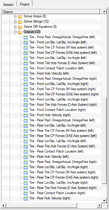 Figure 1.