Deformable Bodies
Deformable bodies in multibody systems are those that can be used to model elastic deformation of the bodies of the system. The deformable body connects to its neighboring elements/bodies through interface nodes. The deformable body consists of reduced stiffness and mass matrices, which can be obtained in various ways. Two popular methods for the same are: Craig-Bampton Method and Craig-Chang Method.
-
If the Bodies panel is not currently displayed, select the desired body by
clicking on it in the Project Browser or in the modeling window.
The Bodies panel is automatically displayed.
-
In the Properties tab, check the Flex Body (CMS) box to
make the model flexible.
Note: If the selected body is a pair entity, first distinguish between the Left and Right tabs in the panel, and then edit the properties. Symmetric properties are not applicable for deformable body pair. Deactivate Symmetric Properties before changing a rigid body pair to Flex Body (CMS).Tip:
- The animation scale specifies the scale factor for animating the mode shapes. This information is used only for creating the animation file and is not needed for solver analysis.
- Browse for a graphic file to display the flexbody in the modeling window.
- Activate the Rigidify check box to consider the flexbody as rigid with the mass inertia properties from the flexbody data.
- Activate the Include geometric stiffening check box to include geometric stiffness data. This option will only be active if geometric stiffness data is available in the flexbody H3D. This option is available in the MotionView solver mode only.
- Click the folder icon to browse and select a Flexbody property file (H3D file) from OptiStruct.
-
Click Nodes on the Properties tab.
The Nodes dialog is displayed.
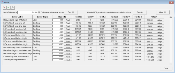
Figure 1.For each marker, a node needs to be specified that will act as an interface between the connecting entities and the deformable body.
-
Find the interface nodes in the deformable body.
- Click Find All and MotionView will find the interface nodes which are closest to each of the listed markers of the entities connecting the deformable body.
- Click Find and look for interface nodes for each marker individually.
Note: The flexbody H3D file for the deformable body contains two types of nodes: interface nodes and non-interface nodes. The interface nodes are those which have been selected to be the interface nodes while creating the flexbody file. These are the nodes which connect the flexbody to the rest of the model. The Only search interface nodes check box specifies that only the interface nodes are to be searched. This ensures that the nodes are found quickly. -
Review the interface nodes that are found.
If the Offset column, a measure of the difference in the point and the node coordinates, shows the offset as 0.000 or 0.001 (this generally happens due to differences in rounding off significant digits), it means that the interface nodes coordinates and the marker origin coordinates are at the same location.
If the offset value is significantly large, a review of the connecting entities, deformable body position, and node coordinate position is recommended. A large offset value could cause difficulties for the solver or may lead to erroneous results.
-
Click the Align button at the end
of each row to align the point coordinate with that of the node.
CAUTION:This option should be used with significant caution, as it causes the point referenced by the connecting entities to change its position and might affect other entity definitions.
-
Click Create (located in the
top-right corner of the dialog) to create points at the interface node
locations.
This is particularly useful when you need to create points at the interface node location for adding joints or other elements that interact with the deformable body.
- Click Close to exit the dialog once all operations are completed.
- From the Deformable Body panel, click Modes to display the Modes dialog.
-
Use the drop-down menu to select a desired deformable body modal damping
type.
Note: The Modes dialog also shows the modes that belong to the deformable body and gives information about the model frequency. By default, the first six modes whose frequencies are zero (or close to zero) are not selected. This is because the rigid modes of the deformable body should be used when solving the model in MotionSolve. Further, you can deactivate any mode that you think should not be included in the model. This should be done by advanced users only!
- Edit the properties of several bodies simultaneously by using the Data Summary dialog.
- Click the FEM Inertia Props tab.
- Enter values for Mass, Inertia Tensor, and CM.
-
Define the body coordinate system.
- Click on the Body Coordsys tab.
- Click the Use body coordinate system check box.
- Click Point and make your selection in the modeling window or the Model Tree.
- Use the orientation options to orient the coordinate system.
-
Define initial conditions.
- Click the Initial Conditions tab on the panel.
- Activate the desired check boxes and enter values for translational and rotational velocity.
-
Select a marker for VM and WM.
Note: The translational initial conditions for a body are assumed to be with respect to the global reference frame in absence of a unique VM (linear velocity reference marker), and the rotational initial conditionals are applied about the center of mass maker in absence of a unique WM (angular velocity reference marker).