Bodies
Use the Bodies tool to create and edit rigid, point mass, and deformable/flexible bodies.
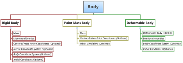
Figure 1.
Rigid Body
In a multibody system, a rigid body is an ideal representation of solid body/part of fixed size and shape in which deformation is insignificant or neglected, or in other words, the distance between any two points of a rigid body remains unchanged (irrespective of the external forces acting on it).
A rigid body will have six degrees of freedom (DOF) and therefore every additional rigid body in a multibody system adds an additional six DOF to the system.
The rigid body can be of two types: movable and fixed. The fixed type of rigid body is also called a ground body. The ground body represents the Newtonian reference frame. It is, by default and definition, at complete rest. In HyperWorks, the ground body exists by default in every model.
Deformable Body (also known as Flexible Body)
Deformable bodies in multibody systems are those that can be used to model elastic deformation of the bodies of the system. The deformable body connects to its neighboring elements/bodies through interface nodes. The deformable body consists of reduced stiffness and mass matrices, which can be obtained in various ways. Two popular methods for the same are: Craig-Bampton Method and Craig-Chang Method.
Properties of a deformable body are defined using a flexbody H3D file. The flexbody H3D file is created using the component mode systems method of FE analysis. Flexbody H3D files can be created using the Altair OptiStruct FE Solver. In MotionView, the utility flexbody prep can be used to create flexbody files from FE models.
MotionView supports creation of the above types of bodies described as a single body or a pair body. For a pair body, the properties can be made symmetric to the global ZX plane (except for a deformable body pair).
Point Mass Body
The point mass body is a reduced version of the six DOF rigid body. It only has three translational DOF, therefore the point mass body has mass, but no inertia properties. The position of a point mass is defined by a center of mass point. By default, the orientation of the point mass is set to be the same as the global coordinate system (which never changes during simulation). The purpose of a point mass entity is to add additional representative weight to another body, for example the mass of a driver on a seat.
NLFE Body
NLFE stands for Non Linear Finite Elements. The NLFE implementation in MotionView/MotionView is based on Absolute Nodal Coordinate Formulation or ANCF. In this approach, only absolute coordinates and global slopes are used to define the element nodal coordinates without the need for using infinitesimal or finite rotations.
In complex multibody simulations, flexible bodies are needed to improve model fidelity. In cases where the deformations and rotations are expected to be large and/or exceed linear assumptions, NLFE becomes a necessity. NLFE can be employed in many application such as cables, belt drives, leaf springs, twist beams, stabilizer bars, coil springs, and many more.
In addition to this, the application of NLFE does not need a reduction analysis to be performed before being used in a model. Also, the implementation is simple enough to enable the user to model subsystems much faster than traditional FE methods. All of this reduces the model-solution turnaround time.