Points

Use the Points tool to create and edit individual points, points on a vector, points along a curve, points at the center of a circle, and parametric points.

Create Points

Add a point to the model with the Points tool.

  1. From the Browser, select the system to which the point entity is to be added.
    The Model label means that the point will be created in the main model.

    By default, points are created in a model level Cartesian coordinate system called the Global Reference Frame. This is the only coordinate system currently available.

  2. From the Geometry ribbon, Points tool set, click the Points icon.
    A guide bar for entity creation appears.
  3. Optional: Activate the Pair check box to create a pair entity.
    A point entity, like most of the entities that are created in HyperWorks, can be a single entity or a pair entity. Pair entities help to create models that are symmetric about the Z-X plane of the model. Their properties can also be symmetric about the Z-X plane (in other words, the Y property is mirrored). Asymmetry or symmetry of the points can be decided or specified when editing the created point.
  4. Pick and existing point or a CAD point.
    • Select a point in the modeling window.
    • On the guide bar, click the Advanced Selector and make your selection in the Model Tree.
    • Click on an empty location in the modeling window to create a new point at that location.
    Once the point has been added to the model, the corresponding point will automatically be displayed in the browser area.
    Note: By default, variables names of entities in MotionView follow a certain convention. For example, all point entities have a variable name starting with 'p_'. This is the recommended convention to follow when building models in since it has many advantages in model editing and model manipulation.
  5. Click the System collector to identify the system or container into which the point will be created.
Tip: A new point can be created from the Project Browser by right-clicking on the Model label (or any system/analysis of your choice) and selecting Add > Reference Entity > Point or by right-clicking Points and selecting New Point.

Create Points on a Vector

Use the Create Points on a Vector tool to create a set of points along a vector.

  1. From the Geometry ribbon, Points tool set, click the Create Vectors of Points icon.
  2. In the Points panel, select one of the two creation methods below:
    If Define vector using points is chosen:
    1. Click the first Point/Node collector and select a point/node from the modeling window, or double-click the collector to display the Model Tree (from which the desired point/node can be selected).
    2. Repeat for the second node collector.
    3. Click the System collector and specify the system attached to the model.
    4. Specify the number of points to create.
    5. Specify the desired prefix for the label and variable name.
    6. Click Create Points.
    Tip: By default the new point locations will be a parametric function of the original points. Activating the Keep values as parametric equations check box allows you to used the calculated point locations directly.
    If Define vector using base point and vector is chosen:
    1. Click the Point/Node collector and select a point/node from the modeling window, or double-click the collector to display the Model Tree (from which the desired point/node can be selected).
    2. Click the Vector collector and select the vector attached to the model from the modeling window or Model Tree.
    3. Click the System collector and specify the system attached to the model.
    4. Enter a value for the distance between the created points.
    5. Specify the number of points to create.
    6. Specify the desired prefix for label and variable names.
    7. Click Create Points.

Create Points Along a Curve

Use this utility to create a set of points along a curve.

  1. From the Geometry ribbon, Points tool set, click the Create Vectors of Points icon.
  2. In the Points panel, select Create points equally spaced along a curve.
  3. Specify the number of points to create.
  4. Specify the desired prefix for the label and variable name.
  5. Enter a value for the number of points used to create the curve fit.
    Note: A minimum number of four points is required to create a curve fit.
  6. Click the Point/Node collectors and select a point/node from the modeling window, or double-click the collectors to display the Model Tree (from which the desired point/node can be selected).
    Note: The number of collectors displayed will match the number input into the Points for curve fit text box.
  7. Click Create Points.

Create Points at At Arc Center

Use this utility to create points at the center of an arc.

  1. From the Geometry ribbon, Points tool set, click the Create Vectors of Points icon.
  2. In the Points panel, select Create point at center of circle.
  3. Click the first Point/Node collector and select a point/node from the modeling window, or double-click the collector to display the Model Tree (from which the desired point/node can be selected).
  4. Repeat for the second and third Point/Node collectors.
  5. Click the System collector and specify the system attached to the model.
  6. Specify the desired prefix for the label and variable name.
  7. Click Create Points.

Create Parametric Points

Use the Parametric Points dialog to create a set of points with respect to a reference marker either in Cartesian coordinates or cylindrical coordinates.

  1. From the Geometry ribbon, Points tool set, click the Parametric Points icon.
    The Parametric Points dialog opens.
  2. Click the System collector to identify the system or container into which the marker will be created.
    The label Model means that the marker will be created in the main model.
  3. Click the Marker collector and select an entity in the modeling window, or double click the button and make your selection from the Model Tree.
  4. Select a coordinate system.
    Note: If you select Cylindrical, specify between degrees and radians.
  5. Define mirrored points.
    1. Check the Create mirror points about marker plane box.
    2. Select a marker plane from the drop-down menu.
    3. Select whether to create a single point or a point pair.
      A point entity, like most of the entities that are created in HyperWorks, can be a single entity or a pair entity. Pair entities help in creating models which have symmetric properties.
    4. Specify a label suffix and a varname suffix.
  6. Specify a varname prefix for the point(s).
    By default, variables names of entities in MotionView follow a certain convention. For example, all point entities have a variable name starting with “p_”. This is the recommended convention to follow when building models in MotionView since it has many advantages in model editing and model manipulation.
  7. Specify a label prefix.
  8. Enter the amount of points to be created.
  9. Define the point(s).
    • Enter the coordinates for each point.
    • Upload a .csv file containing point coordinates.
  10. Click OK to close the window or Apply to continue creating entities.

Create Curve From Points/Nodes/Edges/Faces

The Create Curve From Points/Nodes/Edges/Faces macro allows you to create curve graphics from a set of selected points or nodes, or extract a curve from an edge/face of a geometry represented through CADGraphics.

The generated curve graphics can be used to setup 2D Rigid to Rigid Contact or Advanced Joints, such as Point to Curve or Curve to Curve Joint.

Create Curve From Points/Nodes

Use the Points/Nodes option in the drop-down menu to create a curve graphic using points or nodes.


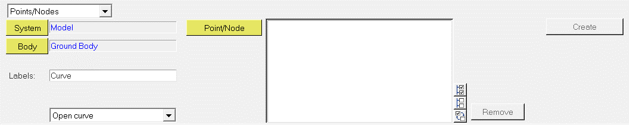
Figure 1. Macro to Create Curve Graphic From Points/Nodes
Option Description
System Use the System collector to select the system in which you want to place the curve graphics.
Body Use the Body collector to select the body with which the curve graphics will be associated.
Labels Allows you to input the prefix for curve and the curve graphics that will be automatically created.
Open/Closed curve Allows you to leave the ends of curve open OR generate a closed curve by automatically joining the first and the last point/node.
Point/Node Use the Point/Node collector to select the points/nodes that will be used to generate the curve.

Use the Remove button to remove single/multiple selections of points/nodes from the panel list.

The All , None , and Reverse options are also provided to allow you to quickly select a set of points/nodes from the list already selected in the panel that you would like to remove from the panel.

Create Use the Create button to run this macro and create the curve and the graphics once you are done selecting the points/nodes and providing other details related to the curve.

Create Curve from Edges/Faces

Use the Geometric Edges/Faces option in the drop-down menu to create a curve graphic by picking an edge or face of a geometry represented through a graphic of the type CADGraphics.


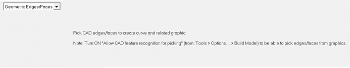
Figure 2. Macro to Create Curve Graphic From Edges/Faces
To use this option, Allow CAD feature recognition for picking must be turned ON in Tools > Options > Build Model.


Figure 3. Create a curve graphic from an edge


Figure 4. Create a curve graphic from a series of edges


Figure 5. Create a closed curve graphic from edges forming a face of the geometry

Edit Points

Change the coordinates of a point.

  1. Select the desired point by clicking on it in the browser or in the modeling window.
    The Property Editor is displayed at the bottom of the browser.
  2. Use the Property Editor to modify the entity data.
  3. If the selected point is a pair entity, first distinguish between the Left and Right, and then edit the properties.
  4. Change the label and variable name.
  5. Activate/deactivate the point in the modeling window.
  6. Use the Property Editor to edit the point's coordinates.
  7. Click in the fields for the X, Y, and Z coordinates and enter a value for each coordinate.