Vectors

Use the Vectors tool to create and edit vectors.

Vectors are entities that can be used for orienting other entities such as joints, bushings, beams, coil springs, etc. Vectors provide direction and have no particular location in space.
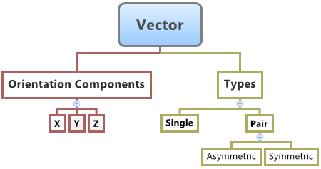
The topological information required to define a vector is shown in the figure below:


Figure 1.

You can create single vectors and pair vectors (asymmetric or symmetric) in HyperWorks.

When used to orient entities in MotionView, the corresponding axis of the markers of the entity (the primary axis that defines the entity direction) gets oriented in the same direction as that of the vector. For example, when a vector is used to orient the direction of the revolute joint, the Z axis of the joint I and J markers are oriented along the direction of the vector.

Create Vectors

  1. From the Project Browser, select the system to which the vector is to be added
  2. Right-click on a system folder in the Project Browser and select Add > Reference Entity > Vector from the context menu.
    OR
    Right-click on a vector folder in the Project Browser and select Add Vector from the context menu.
    OR
    From the Geometry ribbon, click the Vectors icon.
    The Add Vector or VectorPair dialog opens.
  3. Click the System collector to identify the system or container into which the vector will be created.
  4. Specify a label and variable name.
    By default, variables names of entities in MotionView follow a certain convention. For example, all vector entities have a variable name starting with “v_”. This is the recommended convention to follow when building models in MotionView since it has many advantages in model editing and model manipulation.
  5. Select whether to create a single vector or a vector pair.
    A vector entity, like most of the entities that are created in MotionView, can be a single entity or a pair entity. Pair entities help in creating models which have symmetric properties.
  6. Click OK to close the window or Apply to continue creating entities.

Edit Vectors

  1. If the Vector panel is not currently displayed, select the desired vector by clicking on it in the Project Browser or in the modeling window.
    The Vectors panel is automatically displayed.
  2. Enter a value for the X, Y, and Z components in the Properties tab.
    Note: If the selected vector is a pair entity, first distinguish between the Left and Right tabs in the panel, and then edit the properties. Checking Symmetric properties will prompt a dialog where you can make the values symmetric with respect to either side.
Tip: Vectors can be edited in groups using the Vectors tab in the Data Summary dialog.