Markers
Use the Markers tool to create coordinate systems and reference frames.
A marker entity is an orthonormal, right-handed coordinate system and reference frame in MotionView. A marker must belong to a body. The body can be any type: rigid, flexible, or point mass. The default marker that belongs to the ground body (Newtonian reference frame) at the global origin is called global frame.
The topological information required to define a marker is shown in the figure below:
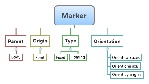
Figure 1.
- Non-Floating (single or pair)
- Floating (single or pair)
A fixed marker belonging to a body is fixed with regard to the body’s reference frame. To attach a marker on a body, a location and orientation need to be specified.
Even though a floating marker belongs to a body, it is not fixed within the body reference frame. Floating markers are generally used in entities such as a vector, force, or a bushing.
Marker is a primary entity in a multibody system. All entities that comprise of a multi-body system are represented in the solver using markers. For example, a CG marker represents a body at the specified marker location and the mass is assumed be located at the origin of the CG marker. A revolute joint is represented by imposing constraints along five directions between two markers (referred as I & J markers), each on the two bodies between which the joint is defined. A similar concept exists for other entities, such as forces. Some entities, such as vectors, forces, or bushings require their J marker to be coincident with the I marker. Hence the J marker needs to move with respect to its body reference frame, thereby such markers are defined as floating markers.
While defining entities such as bodies, joints, and forces in MotionView, markers are implicitly created. However, there are occasions where markers need to be explicitly created. For example, to define an output at a certain location where there are no other entities, or to define a reference frame for a force.
Create Markers
A marker is a coordinate system attached to a body that is used as a reference for other entities such as joints, forces, motions, and output requests.
-
Select a body reference.
- Select a body in the modeling window.
- On the guide bar, click the Advanced
Selector
 and make your selection in the Model Tree.
-
Select an origin reference.
- Select a point in the modeling window.
- On the guide bar, click the Advanced
Selector
and make your selection in the Model Tree.
- Optional:
Click
 to reset the entity selections and select new
entities.
to reset the entity selections and select new
entities.
-
Once the reference selections are made, create the marker using one of the
following methods:
- Click
 on the guide bar to create and orient the
entity.
on the guide bar to create and orient the
entity. - Click the
 button that appears at the mouse location in
the modeling window.
button that appears at the mouse location in
the modeling window. - Click
 to create the entity and exit the guide bar selections for this marker.
Once the marker has been added to the model, the corresponding marker will automatically be displayed in the browser area.Note: By default, variables names of entities in MotionView follow a certain convention. For example, all markers entities have a variable name starting with 'm'. This is the recommended convention to follow when building models in since it has many advantages in model editing and model manipulation. - Click
Edit Markers
In addition to specifying an associated body and an origin, you must specify the axes' rules to define a marker.