Auto Midsurface Tool

Use the Auto Midsurface tool to extend and modify midsurfaces.

Auto Extraction Subpanel

Use the Auto Midsurface subpanel to extract the midsurface of a more complicated group of surfaces that represent a solid part in one step.
Option Action
entity selector Select the surfaces or solids from which you wish to extract midsurfaces.
closed solid / incomplete solid
closed solid
Select a single surface of the solid geometry and click extract. The enclosed volume the selected surface belongs to is automatically determined, and the midsurface is extracted from it.
incomplete solid
Enable additional options for selecting and orienting the surfaces defining the body to extract.
select connected surfaces Automatically select all of the attached surfaces once you select a single surface.
Note: Only available when incomplete solid is selected.
outbound normals (red) Indicate that the normals of the selected volume point outside the enclosed volume. Clear this checkbox when the normals point inside the enclosed volume.
The normals of the selected surfaces are displayed as soon as your selection is completed.
Note: Only available when incomplete solid is selected.
color display normals / vector display normals Choose how the normal direction of the selected surfaces is displayed. Color display is recommended.

When normals are consistent, color display normals colors the outer surfaces of the model red or blue, but never a mixture of both. For most models, normals are automatically oriented consistently.

fix normals / reverse normals Reorient surfaces that do not have a consistent normal direction.
fix normals
Automatically fix the normals of all the surfaces in the selection.
reverse normals
Reset your surface selection and select the surfaces for which normals need to be adjusted if surface normals are inconsistent.
The consistent orientation of normals (either all normals pointing outside the part, or all pointing inside the part) is crucial for the success of the midsurface extraction.
extract Extract the midsurface.

Extraction Options Subpanel

Use the Extraction Options subpanel to define midsurface extraction settings.
Option Action
offset + planes + sweeps / offset + planes / offset / skin offset
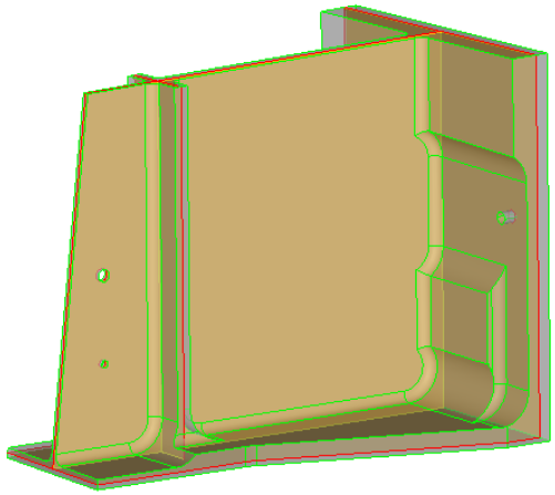
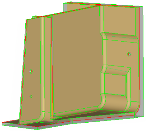
offset + planes + sweeps
Identify the places where a piece of plane or a piece of a sweep surface can be used as a middle surface. A middle surface is constructed at the remaining places in the model, for example the places where planar or sweep surface pieces cannot be used as a middle surface, by the same algorithm as in offset via the offset of the model's sides.


Figure 1.
offset + planes
Identify the places in the model where a piece of plane can be used as a middle surface. At the remaining places in the model, for example the places where planar pieces cannot be used as a middle surface, the same algorithm as in offset is used to construct the middle surface via the offset of the model's sides.


Figure 2.
offset
Create pieces of the middle surface by offsetting the model's side surfaces towards the middle. This is the traditional approach for midsurfacing in HyperMesh.


Figure 3.
skin offset
Method description: The "skin offset" method automatically detects the two largest faces on the model, detects the thickness, and then creates the middle surface by offseting one of the faces towards the other one by half of thickness. This is the quickest method for creating a midsurface. However, it is not applicable to many models.
Assumptions:
  • There are smooth transitions along the faces. Sometimes, certain non-smooth transitions may be handled by increasing the default geometry feature angle.
  • There are no smooth transitions at edges/holes from one face to another one, the transitions should be sharp enough.
  • No ribs are present. There should only be one face(plate) in the input.
  • No variations in thickness are taken into account.
The typical models where "skin offset" can be successfully applied are metal stamped parts.
Figure 4.
align steps/keep step jumps In the case of a part that has different "steps" of thickness, such as a flat sheet that is twice as thick at one end as the other, but uses an abrupt step-like change in thickness instead of a constant slope or curve choose how to manage steps.
align steps
Align midsurfaces.
step jumps
Produce steps between the various midsurfaces as in the original model.
When align steps is selected, this option and all of its sub options (user mid position/auto mid position, and the value for the user-specified mid-position) will only be executed during midsurfacing when there is a single surface on one side, and several surfaces located at different distances (thus forming steps) in front of the single surface.


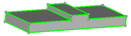
Figure 5. Valid Steps. Steps are in Front of a Single Surface
If steps are not in front of a single surface, but instead are in front of several surfaces, then steps will not be recognized as something that can be aligned during midsurfacing.


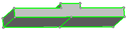
Figure 6. Invalid Steps. Steps are in front of multiple surfaces.
If steps appear on both sides of the expected midsurface, then align steps will be applied, but it is not guaranteed the steps will be aligned during midsurfacing.
Note: Only available when you select offset.
auto mid position / user mid position
auto mid position
Create a midsurface parallel to the largest side of the volume. This midsurface includes "offset" data to represent the changes in distance between the midsurface and the smaller faces at each "step".


Figure 7. . The midsurface (with orange nodes) is parallel to the larger face of the solid plate.
user mid position
define the offset of the midsurface, using a value from 0 to 1, in order to specify the offset from the largest side of the volume.
Note: Only available when you select offset and align steps.
allow rerun Go to the Edit Collapsed Lines subpanel, from which you can enable visualization settings to display point associations on the midsurface after extraction, and create and edit collapsed lines.

When extracting a new midsurface, the midsurface is generated using the collapsed lines that were automatically found during the initial midsurface extraction and the lines that you manually collapsed.

If allow rerun is disabled or the allow rerun switch is set to no rerun or prepare for rerun, then the lines that you manually collapsed will not be used when a new midsurface is extracted.

use base surfaces Go to the Edit Base Surfaces subpanel, from which you can specify a distance from the base surfaces of multiple solids, that you wish to treat as if they were continuous, in order to generate separate-but-aligned midsurfaces during extraction.

If use base surfaces is disabled, new midsurfaces will not be generated at the specified distance from the selected base surfaces. The setup of the base surfaces that you modified will be retained for future use as long as you do not delete them.

thickness bounds/no thickness bounds Choose whether or not to specify thickness bounds for the plates in the part.
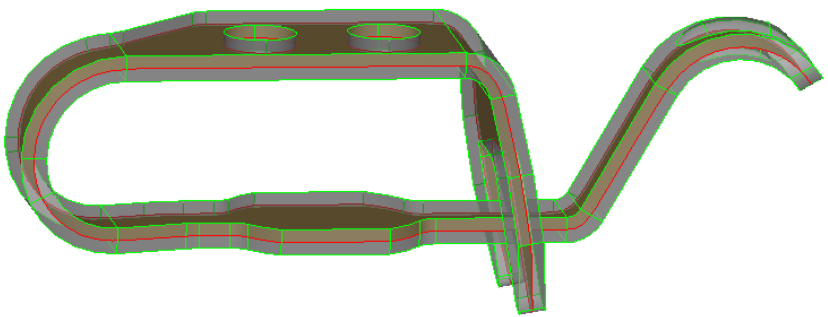
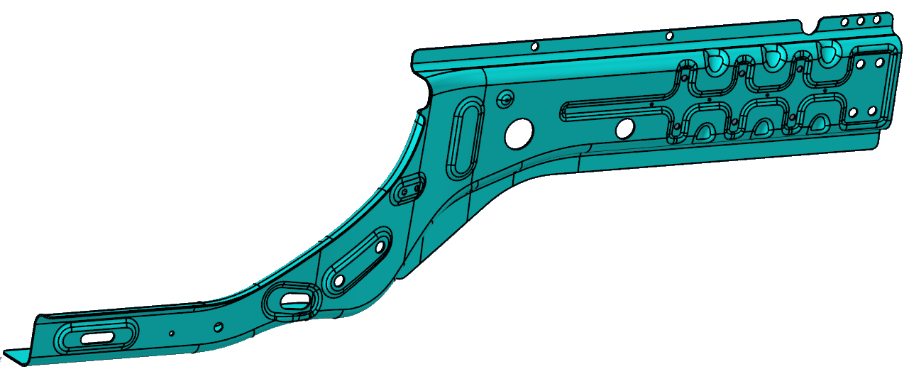
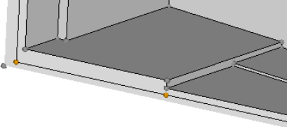
thickness bounds
Specify a minimum and maximum thickness of the plates in the part.
Middle surfaces are only created for plates with a thickness that falls into the specified range. Thickness bounds can improve the robustness of the results and speed up middle surface creation; however, you must be sure that you do not cut off some plates by selecting thickness limits that are too narrow.
no thickness bounds
Specify a max thickness ratio for midsurface extraction.
This is the highest acceptable ratio of the thickest plate's thickness to that of the thinnest plate. Plates whose thickness is greater than this value multiplied by the thinnest plate's thickness is ignored. Using too small of a value can cause incorrect midsurface extraction. However, larger ratios take more time to process.
max R/T ratio This ratio is taken into account on T-, X- and more complex connections only. On a curve without a T-connection (like on the right side on the picture) it does not apply.
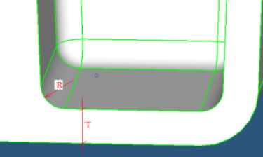

Figure 8.
If R/T is greater than the specified value, then this location will not be recognized as a junction and will be considered as a solid piece. If T is different on different sides on the junction (as in the above picture), then the maximum T is used.

Since in many cases the fillet is not an exact cylinder and has a variable curvature, or the fillet cross-section is not orthogonal to the fillet axes, in reality the length on the curve at the fillet is taken and R is recalculated from this length as if it were an arc of a circle.

thickness based stitch tol Perform the final stitching of midsurfaces with a locally-defined tolerance of 1/5 of the local thickness.

Clear this checkbox to use the global cleanup tol specified in the Options panel for stitching. This method is recommended when an extensive manual edit of the auto midsurfacing result is expected, because stitching comparatively distant midsurfaces may misrepresent the geometry of the model and affect following operations on geometry.

extract by component/cross components This option is useful when you are trying to extract the midsurface of multiple parts in a single step.
extract by component
If each part is contained in its own component, extract the midsurface of one component at a time.
cross components
If your model contains a single part organized in multiple components.
result in Middle Surface comp/result in current comp / sorted results Choose where to organize midsurfaces upon creation.
result in Middle Surface comp
Organize midsurfaces in the Middle Surface component (Recommended).
result in current comp
Organizes midsurfaces in the current component.
sorted results
Perform midsurface sorting immediately after extraction.
sort Middle Surface comp into Choose how to sort the middle surfaces immediately following extraction.
<~[o]riginal name> comp
Create new components by removing the first letter of the original component name and replacing it with a ~ and sorts the midsurfaces accordingly. For example, my_comp -> ~y_comp.
<Midsurface #nn> comp
Create components with the name Midsurface #, where # increases for each component that exists for the input surfaces/solids.
original comp
Organize the midsurfaces into their parent surface/solid components.
<original name~> comp
Create components using the original component name and adds ~ at the end.
<original nameN> comp
Create new components by incrementing the name of the original.
Tip: Manually sort the Middle Surface component after extraction from the Sort subpanel.

Message Options Subpanel

Use the message options subpanel to select the notifications that you would like to receive during midsurface extraction.
  • Plate type change
  • Deleting plate information
  • Pre-existing plates/base surfaces
  • Plates/base information conflicts