CFD Tetramesh Panel
Use the CFD Tetramesh panel to generate hybrid grids, containing hexa/penta/tetra elements in the boundary layer and tetra elements in the core or fare field.
Location: 3D page
Buttons to mesh, reject a mesh, mesh to file, or check 2D mesh exist on all subpanels except for the Refinement box, meaning you have access to the meshing functionality from almost each subpanel. You can mesh from one of the parameter panels, and if the mesh results are not satisfactory, you can reject the mesh, change some parameters and regenerate the mesh without leaving the subpanel.
Boundary Selection Subpanel
| Option | Action |
|---|---|
| Advanced select / Simple select | Choose a method for
selecting boundary regions.
|
| Smooth BL / Smooth/Truncate BL / Native BL |
|
| With BL (fixed/float) | Select tria/quad
elements that define the surface area on which you need to
generate boundary layers. If a refinement box includes boundary shells selected via the With BL (float) selector and the remesh option is used, the surface elements are remeshed using the element size assigned to the refinement box. |
| W/o BL (fixed / float) | Select tria/quad
elements that define the boundary regions where a boundary layer
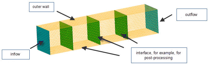
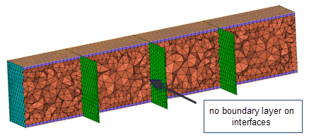
is not desired. The option W/o BL (fixed) can be used, for example, if two adjacent volumes are meshed sequentially and a matching interface has to be ensured. In that case the common interface elements have to be selected as W/o BL (fixed). |
| Remesh/Morph |
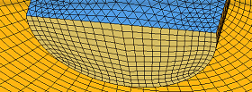 Figure 3. Starting Surface Mesh. The symmetry plane is blue, and the inlet area is dark yellow. 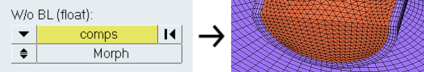 Figure 4. Resulting Mesh, Morph Selected 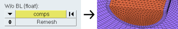 Figure 5. Resulting Mesh, Remesh Selected Note: Available when Smooth BL is selected.
|
| swap only / remesh | Choose a method for
managing the edges of the base 2D mesh in order to produce
better quality 3D tetra elements.
|
| fix comp borders | Maintain anchor nodes
during CFD tetrameshing, so that the new mesh must adhere to
them. You can also select 1D elements instead of nodes if you
need a tetra element edge at a certain location. Tip: Use this option when certain mesh nodes or edges
are required on a certain location, such as for
post-processing purposes.
If the float option is chosen for some boundary regions, HyperMesh is allowed to swap surface shell edges during mesh generation. However, this prevents the swapping of edges between two components. 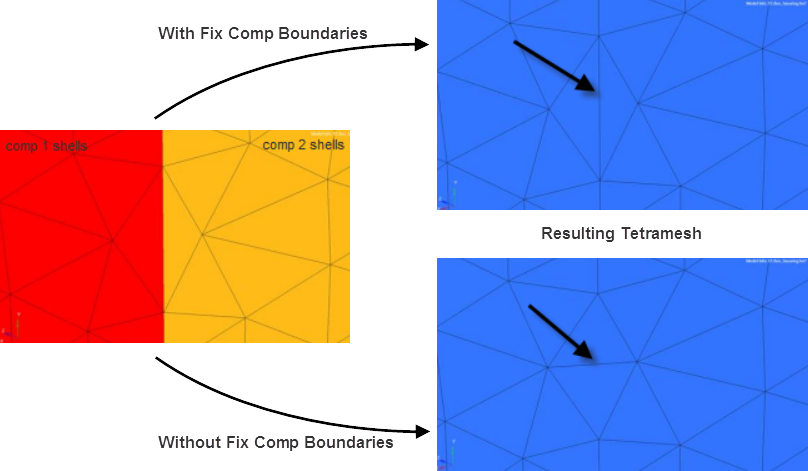 Figure 6. Example: Fix Comp Borders |
| update input shells | Automatically update the shells on all boundaries after the meshing step. The updated shell elements will be placed in the initial boundary shell components. |
| fluid volumes selection | Specify fluid and solid volumes if multiple volumes exist.
The boundary layer will be grown only in the fluid volumes,
whereas the solid volumes are filled with a pure tetra mesh
without boundary layers. The use case is electronic cooling,
where you have several electronic components (solids) and
usually one large fluid domain.
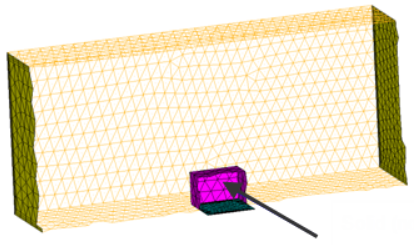 Figure 7. Solid (no BL) 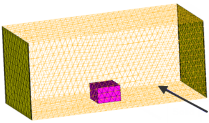 Figure 8. Fluid (with BL) 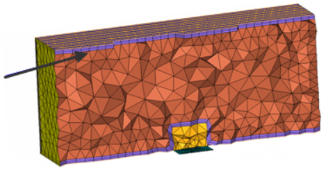 Figure 9. BL Only in Fluid Domain |
| anchor nodes | Maintain anchor nodes during CFD tetrameshing, so that the new mesh must adhere to them. You can also select 1D elements instead of nodes if you need a tetra element edge at a certain location. Use this option when certain mesh nodes or edges are required on a certain location, such as for post-processing purposes. |
| comp per volume | Meshing multiple volumes with CFD Tetramesh will create two
components for each volume, one for the boundary layer elements
and one for the core (tetra) elements. For pure tetra meshing
only one component per volume will be generated. Enable this checkbox to generate several components. 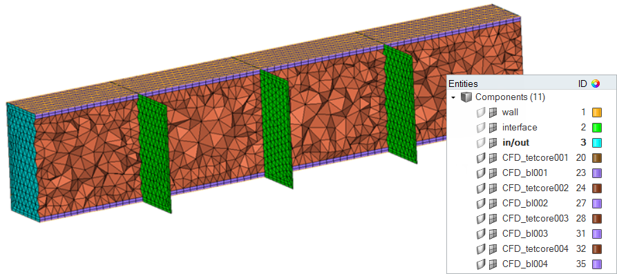 Figure 10. Example: Comp Per Volume |
BL Parameters Subpanel
| Option | Action |
|---|---|
| BL thickness: Number of Layers | Specify the total
number of layers to be generated using the specified first layer
thickness and growth rate. Note: Available when Smooth BL is
selected.
|
| BL thickness: Total Thickness | Specify the BL
thickness, but not the number of layers. Note: Available when
Smooth BL is selected.
|
| BL thickness: Ratio of Total Thickness/Elem Size | Specify the ratio
between the total boundary layer thickness and the average
element size of the base surface elements. Note: Available when
Smooth BL is selected.
|
| Exponential Boundary Layer / Structured Isotropic Layers | Choose between
Exponential Boundary Layer and Structured Isotropic
Layers. Note: Available when Native BL is
selected.
|
| Simple settings | Grow BL until it
matches final layer height/base surface size ratio. The number
of layers to grow are decided based on the inputs.
Note: Available when Smooth/Truncate BL is selected.
|
| User controlled | Define settings for
two BL groups. The purpose of the first BL group is to define BL
with a smaller growth rate to better physics capturing. The
second group enables a smooth transition between BL layers and
the tet core. User controlled enables BL to grow with a higher
growth rate until the final layer height is X * the base
size/tetra layer size. (X is the Final layer h/base ratio that
you define.) Note: Available when Smooth/Truncate BL is
selected.
 Figure 11. Example: User Controlled. The first arrow indicates the second BL group, where the number of layers = 4 and the growth rate = 1.5. The second arrow indicates the first BL group, where the number of layers = 8 and the growth rate is 1.1. |
| First layer thickness | Specify the thickness
of the first layer. This utility helps you estimate the proper first cell height (first layer thickness) for the boundary layer generation, based on the flow characteristics and fluid properties. You can open this dialog by clicking on the 1st cell height calc icon on the BL Parameters subpanel. The entry fields on this dialog are actually settings for the Calculate first layer thickness button. Once you supply the required data, clicking this button causes the dialog to automatically calculate and suggest an appropriate thickness.
Once all of these qualities are specified, clicking Calculate first layer thickness produces a suggested thickness. You can either Accept this value, in which case the window closes and the value is automatically placed into the First layer thickness field of the CFD Tetramesh panel, or you can click Close to close the window without accepting the suggested value. |
| BL growth rate | Specify the non-dimensional factor that controls the change in layer thickness from one layer to the next. |
| Acceleration | A growth acceleration for boundary layers beyond the first
few layers; in effect, this acts as a growth rate on the growth
rate, but only after the first few initial boundary layers. By
default, the first two boundary layers grow by the growth
rate as described above. However, subsequent layers grow by
the growth rate multiplied by the acceleration factor. Thus,
if d is the initial thickness, r is the initial growth rate,
and a is the acceleration rate, then the thicknesses of the
successive layers are d, d*r, d*r*(r*a), d*r*(r*a)^2, and so
on.
Note: Available when Native BL is selected and
Exponential Boundary Layer is chosen.
|
| BL hexa transition mode: Simple Pyramid | Use one pyramid element to transition from a BL hexahedral’s
quad face to the tetrahedral core mesh. The height of these
pyramids is controlled by simple transition ratio parameter,
which represents the ratio between the transition pyramid height
and the characteristic size of the base quad. Note: Available
when Smooth BL is selected.
|
| BL hexa transition mode: Smooth Pyramid | Generate a transition layer composed of pyramid and
tetrahedral elements. The thickness of this layer is controlled
by the parameter smooth transition ratio, which represents the
ratio between the transition layer thickness and the
characteristic size of the base quads. Note: Available when
Smooth BL is selected.
|
| BL hexa transition mode: All Prism | If there are quad elements in the surface mesh, those will be
split into two trias each so that there is no need to transition
from quad faces to tria faces when transitioning from the last
boundary layer to the tetrahedral core. This option is very important when there are quad elements on areas with (low) distributed BL thickness ratio, because in such areas the thickness of the transition elements (for example simple pyramid) was not taken into account when doing the interference study to assign distributed BL thickness ratio to those elements. Note: Available when Smooth BL is
selected.
|
| BL hexa transition mode: All Tetra | Generate tetra elements only in the boundary layer, and split
the quad elements of the surface mesh into tria
elements. Note: Available when Smooth BL is selected.
|
| Export settings | Save the settings to a file. |
| Create prism elements | Clear this checkbox to create tetra elements rather than
triangular prisms during meshing. Note: Available when Native BL
is selected.
|
| BL only | Generate only the boundary layer, stopping before generating
the tetrahedral core. It also modifies adjacent surface meshes
to reflect changes introduced by the boundary layer thickness,
and creates a collector named ^CFD_trias_for_tetramesh that is
typically used to generate the inner core tetrahedral mesh using
the Tetramesh parameters subpanel. Boundary layer elements are placed in a collector named CFD_boundary_layer and the core tetrahedral elements in another collector named CFD_Tetramesh_core. Both collectors are automatically created if they do not exist. However, if these collectors do exist, it might make sense to empty them before meshing; otherwise there will be more than one set of elements occupying the same physical volume. If you mesh the volume in several steps (multi-volume meshing), then you might not want to empty the collector before generating the mesh for the next adjacent volume. |
| BL reduction | Define the parameters for scaling the boundary layer
thicknesses to avoid narrow or closed channels. Several BL
reduction mechanisms are available, and can be combined with
each other.
|
| 1st cell height | Calculate the first cell height via the First cell
height dialog. This utility helps you estimate the proper first cell height (first layer thickness) for the boundary layer generation, based on the flow characteristics and fluid properties. You can open this dialog by clicking on the 1st cell height calc icon on the BL Parameters subpanel. The entry fields on this dialog are actually settings for the Calculate first layer thickness button. Once you supply the required data, clicking this button causes the dialog to automatically calculate and suggest an appropriate thickness.
Once all of these qualities are specified, clicking Calculate first layer thickness produces a suggested thickness. You can either Accept this value, in which case the window closes and the value is automatically placed into the First layer thickness field of the CFD Tetramesh panel, or you can click Close to close the window without accepting the suggested value. |
| Advanced settings | Open the Advanced BL parameters dialog,
and define advanced parameters to control the BL. Note: Available
when Smooth BL or Smooth/Truncate BL is
selected.
|
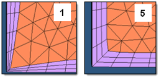
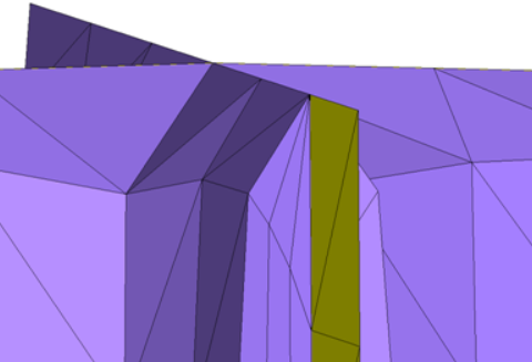
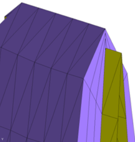
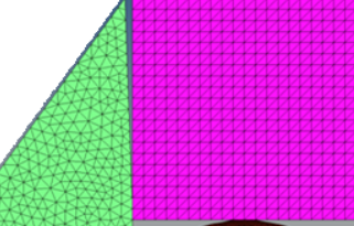 Figure 15. Sharp Corner |
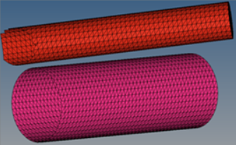 Figure 16. Close Proximity |
| Option | Action |
|---|---|
| BL gen speed vs quality | Select a method for
controlling the growth of the boundary layer.
|
| Interpolated layers (available when User Defined is selected) | Define the number of
layers that are generated by interpolation. For example, for
a value of three, one "thick" layer will be generated and
the smoothing step to improve the element quality will be
performed. Then, the "thick" layer will be split into three
layers, and the spacing is defined by the BL growth rate. In
general a large number of interpolated layers will decrease
the meshing time but might also decrease the element
quality.
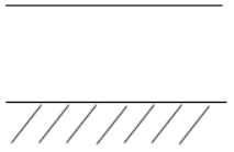 Figure 17. One "Thick" Layer + Smoothing 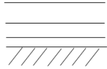 Figure 18. "Thick" Layer is Divided Note: Available when BL gen speed vs quality is
set to User defined.
|
| Residual threshold (available when User Defined is selected) | Define the stopping
criteria (upper bound) for the smoothing step during BL
generation. For each new layer, smoothing steps are applied to
improve the element quality and the overall BL quality. The
smoothing step is an iterative process and the smoothing
residual is a measurement for the quality of boundary layer,
meaning the smaller the residual the better the BL quality. In
general, a small residual threshold ensures good quality of the
boundary layer but might require more CPU time (under the
assumption that the value for maximum smoothing iterations is
set large enough). A relatively large residual threshold will
usually decrease the CPU time and also decrease the element
quality. Note: Available when BL gen speed vs quality is set to
User defined.
|
| Maximum smoothing iterations (available when User Defined is selected) | Define the maximum
number of smoothing steps allowed to improve the element quality
in the boundary layer. Note: Available when BL gen speed vs
quality is set to User defined.
|
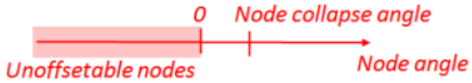
| Sharp edges handling |
|
| Min imprint angle from BL to non-BL | Control which cases
you want to imprint BL on without BL components. If the angle
between the BL component and the non BL component is really high
imprinting will create high aspect ratio elements. If the angle
between BL and No-BL entities (component elements) is less than
the imprint angle or greater than (180-imprint angle) it will
collapse the BL, rather than imprint on non-BL entities. Important: Recommended range is
6-10.
Note: Available when Smooth/Truncate BL is
selected.
|
| Max layer diff between neighbor elems | Control the maximum
layer difference between neighboring elements. This helps to
avoid a situation where all BLs collapse at once. This parameter
also provides smooth BL transition in case of BL truncation. One
fourth of the total BL layers is a good number for this
parameter. It also depends on layer height. Important: Recommended range depends on how many
layers you are growing.
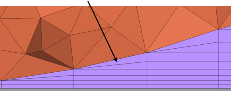 Figure 23. Max Layer Diff Between Neighbor Elems = 2. Two layers are collapsed at a time when required. Note: Available when Smooth/Truncate BL is
selected.
|
| Max BL compression | When there is not
enough space available for BL to grow, this parameter enables BL
compression, or squeezing. Entering a value of zero enforces no
BL compression, which is useful if you want to maintain BL
height. Entering a value of one enables the maximum possible
compression. First, the BL will try to compress by the max BL
compression factor. For example, if the original total BL height
is defined as 1, with 0.4 max BL compression, it will try to
squeeze the BL layers until 0.6 of the total height. After
compressing BL until this value, if there is not enough space
the mesher will start chopping off layers. Important: Recommended range is
0-0.6.
Note: Available when Smooth/Truncate BL is
selected.
|
| Min BL thickness/base size ratio | By default this value
is zero, which disables the effects of this parameter. Sometimes
due to close proximity the BL will only be able to generate one
to two layers (very small total BL height at that location). It
might be possible that at that location the transition between
BL layers and tet core is very bad. With this factor, if the
total BL height is less than the defined factor base size, it
will chop off all of the BL layers. Note: Available when
Smooth/Truncate BL is selected.
|
| Min tetcore/final layer height ratio | After creating BL in
close proximity, there will be a small space available for
tetramesh. This results in high aspect ratio tet elements. This
parameter controls the minimum height of tet core as a factor of
the final layer height. Important: The default value
is 1.3, which is the recommended
value.
Note: Available when Smooth/Truncate BL is
selected.
|
| Max cell skewness | Avoid creating highly
skewed elements. The tetra mesher sometimes creates better
quality elements compared to the BL mesher. It is best to define
a higher value if your input 2D mesh has bad element quality and
topology. Any BL cells exceeding the max cell skewness will be
chopped off. Important: Recommended range is
0.8-0.95.
Note: Available when Smooth/Truncate BL is
selected.
|
| Min normalized Jacobian | Any BL cells exceeding the min normalized Jacobian will be
chopped off. This parameter avoids generating negative elements.
Important: Recommended range is
0.05-0.2.
Note: Available when Smooth/Truncate BL is
selected.
|
Tetramesh Parameters Subpanel
| Option | Action |
|---|---|
| Max tetra size | Specify a size that tetra elements will not exceed in any dimension. |
| Optimize Mesh Quality / TetraMesh Normally / Optimize Mesh Speed |
|
| Growth options |
|
| Uniform layers |
Select how far the constant tetra size should be maintained from the surface mesh during tetrameshing. The distance is internally calculated by multiplying the user defined factor by the local surface mesh size.HyperMesh specifies different default value of this parameter.
|
| Growth rate |
If d is the initial thickness and r is the initial growth rate, then the thicknesses of the successive layers are d, d*r, d*r^2, d*r^3, d*r^4, and so on. If element quality is very important and you are not concerned with the total number of elements created, then Interpolate will produce the best results because the element size changes smoothly and therefore the element quality is better. HyperMesh specifies different default value of this parameter.
|
| Pyramid transition ratio | Specify the relative height of pyramid elements used for the transition from hexa elements in the boundary layer to the tetra elements in the core. |
| Export settings | Save the settings to a file. |
| Refinement box | Specify the refinement boxes which should be considered during volume meshing. Refinement boxes not selected will be ignored. |
| smoothing | Apply an extra stage of calculation to improve overall mesh quality. Additional smoothing and swapping steps will be performed and tetra elements will be split to achieve a smoother mesh transition. If tetra elements are used in the boundary layer those elements will be excluded from smoothing to maintain the original distribution. |
| Number of layers |
Specify the number of tetrahedral layers to generate. The
Tetramesher ensures the tetracore contains, at minimum, the specified number of
tetra layers in the model. This functionality ensures a certain mesh resolution in
case of close proximity or thin channels. When generating multiple tetrahedral
layers, keep the following restrictions in mind:
|
| fill voids | Mesh all volumes, if your geometry includes volumes inside of another volume. For example if you had a sphere inside of a larger sphere, checking this option would cause the volume of the inner sphere as well as the volume between the two spheres to be meshed. |
| Fix Midnodes | In case of 2nd order tetras, this option fixes the mid edge node of surface mesh while volume meshing |
| Elem quality target | Select an element criteria and a threshold. After the tetrameshing step, HyperMesh performs a mesh optimization step to fulfill the defined threshold for the selected element criteria. |
| Min Tetra Height | Generate tetramesh with a minimum height above the value defined. The tetramesh algorithm will try to enforce the user-defined minimum height. |
2D Parameters Subpanel
| Option | Action |
|---|---|
| Select 2D element type | Select a type of 2D elements. |
| Use curvature | Create finer mesh in areas of high surface curvature. |
| Use proximity | Refine the mesh in areas where the features are small and closer together. |
| Element size | Specify the target size for 2D elements. |
| Cleanup elements | Apply an extra stage of calculation to improve overall mesh quality by removing some nodes and combining elements. |
| Export settings | Save the settings to a file. |
Refinement Box Subpanel
| Option | Action |
|---|---|
| Define refinem |
|
| Scaling factor |
Specify the box size relative to the selected elements. A
scale factor of 1 creates the smallest box that can still enclose the selected
elements, while a factor of 2 creates a box twice as large in every
dimension.
Note: Available when Define refinement box is set to By Elems
Box.
|
| Refinement size |
Specify the target element size for mesh inside of the
refinement box.
Note: The actual mesh size will vary in order to
maintain mesh connectivity at the edges of the box.
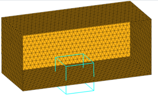 Figure 24. Boundary Region Selected as With BL (flat) and Remesh 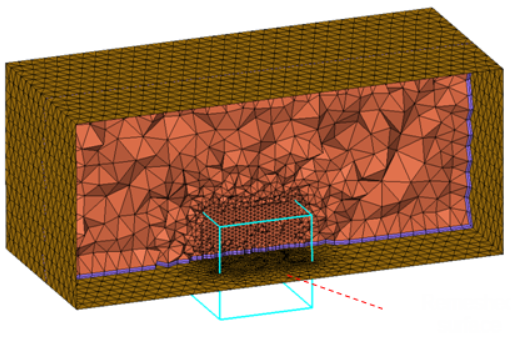 Figure 25. Remeshed Surface. The region included in the refinement box has been remeshed with the elements size assigned to the refinement box. |
| freehand edit | Open the morphing Freehand panel, from which you can alter the shape and dimensions of the refinement box to better suit your mesh. |
Command Buttons
| Button | Action |
|---|---|
| mesh | Generate the CFD mesh. |
| reject | Undo the creation of the mesh, discarding all related elements. |
| mesh to file | Store the generated mesh in a .nas or .hmx file after meshing is finished. When enabled, specify a location to export the mesh. |
| check 2D mesh | Validate the input surface mesh before performing volume mesh generation using the Boundary Shell Checker tool. |
| manual |
|
| auto |
|
| fix 3D elements | Fix 3D elements in the
following ways using the Solid Mesh Optimization tool.
|
| return | Apply all changes and close the panel. |