Organize Panel
Use the Organize panel to (re)organize your database by copying or moving data (entities) among collectors, includes, or parts.
Collectors Subpanel
Use the Collectors subpanel to organize entities such as elements, loads, and systems
into their corresponding components, load collectors, system collectors, and so on.
| Option | Action |
|---|---|
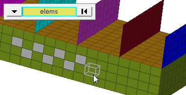
| entity switch | Select an entity type
to copy/move, then use the selector to select specific entities
to copy/move. The current collector serves as the default
destination.
|
| dest component /dest group | Choose a collector to
move the selected entities into. When the entity switch is set to elems, choose between components or groups. |
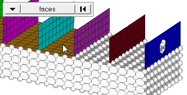
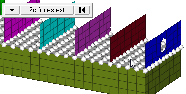
| face angle / individual selection |
|
Includes Subpanel
Use the Includes subpanel to organize all entities in the model such as elements,
components, loads, and materials into an include file or the master model.
Note: Only
valid for solvers that support and preserve includes (such as OptiStruct, Nastran, LS-DYNA).
With this option, a single model can be
organized/sorted into various include files and exported accordingly.
| Option | Action |
|---|---|
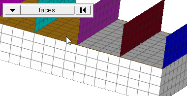
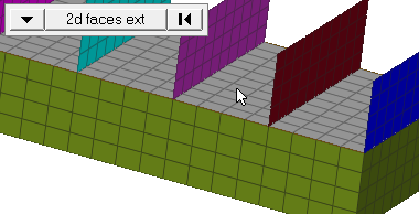
| (entity switch) | Use the switch to
select an entity type to move, then use the selector to select
specific entities to move into the include. When you select
nodes or elems, click the switch to change the selection mode.
|
| dest | Select an include to move the selected entities into. |
| move (nodes, elements, systems, vectors, loads and equations, beamsections) | Move additional
entities (nodes, elements, systems, vectors, loads and
equations, or beamsections) along with the selected parent
collector. By default this checkbox is selected. If cleared,
the above entities may not be moved with the selected parent
collector.
Note: Available when the entity selector is set
to system collectors, vector collectors, load
collectors, beamsection collectors, group, and
components.
|
| face angle / individual selection |
|
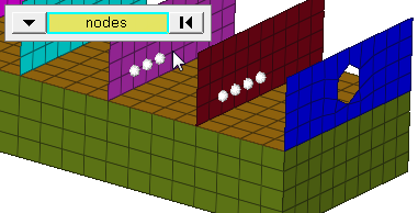
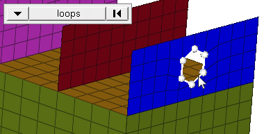
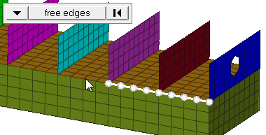
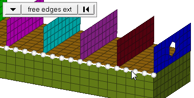
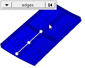
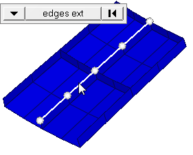
| edge angle |
Split edges that belong to a given face. When the edge
angle is 180 degrees, edges are the continuous boundaries of faces. For smaller
values, these same boundary edges are split wherever the angle between segments
exceeds the specified value. A segment is the edge of a single element.
Important: Only available when the entity selector is set to nodes and the
selection mode is set to free edges, free edges ext, edges, or edges
ext.
|
Parts Subpanel
Use the Parts subpanel to organize and move components into parts.
| Option | Action |
|---|---|
| entity switch | Select components to move. |
| dest module | Select a part to move the selected components into. |
Command Buttons
| Button | Action |
|---|---|
| move | Move the selected entities to the specified collector, include file, or module. |
| copy | Copy the selected
entities to the specified collector, so that they exist in both
the original and new collectors. Entities cannot be copied to an include file or modules. |
| reject | Undo the most recent copy or move operation. |
| locate | Query the database to
determine to which include an entity belongs. To use this option, click locate and then select an entity from the modeling window. The dest field displays the include to which the selected entity belongs. |
| return | Exit the panel. |