Check Elems Panel
Use the Check Elems pane to verify the basic quality of your elements, as well as the geometric qualities of those elements.
Location: Tool page
Each subpanel displays quality checks of a specific type, depending on dimensionality, time steps, and so forth. Each check is listed on a green command button; clicking the button performs a check and the results are summarized in the status bar.
Criteria that you edit will be preserved even if you navigate to a different subpanel and then back again. However, criteria on different subpanels do not relate to each other, so changing the length requirement on the 1-d subpanel does not change the length requirement on the 2-d subpanel.
Different checks are supplied to review the quality measurements of different types of elements. For example, if you have created a quad, it is possible that the quad has some degree of warpage. You can use the warpage function to check the element for warpage and to specify the maximum allowable warpage for that element.
1-d Subpanel
| Option | Action |
|---|---|
| free 1-d's | Check for free ends in 1D elements. |
| free 1-d nodes | Check for free nodes (not connected to another mesh) at the ends of 1D elements. |
| rigid loops | Check 1D rigid elements for rigid loops. 1D rigid elements that build loops are highlighted. Rigid elements are detected as forming a loop if the rigid elements form a closed loop and the dependent node of one rigid serves as independent node of the next rigid in the loop. If memory requirements are exceeded, reduce the number of displayed rigids. |
| dependency | Check 1D weld and rigid elements for conditions causing double dependency. |
| include independent nodes | 1D elements that share a node (dependent or independent) are
considered to fail the check. When this checkbox is cleared, 1D elements that share the same dependent node are considered to fail this check. Thus a rigid element whose dependent node is an independent node of another rigid element does not fail this check. |
| length < | The elements that have a length less than the value specified are highlighted when the length function is selected. These elements remain highlighted until you exit the Check Elems panel or you select another check element function. |
| length > | The elements that have a length greater than the value specified are highlighted when the length function is selected. These elements remain highlighted until you exit the Check Elems panel or you select another check element function. |
2-d Subpanel
| Option | Action |
|---|---|
| warpage | The amount by which an element or element face (in the case of solid elements) deviates from being planar. Warpage of up to five degrees is generally acceptable. |
| aspect | The ratio of the longest edge of an element to its shortest edge. Aspect ratio should be less than 5:1 in most cases. |
| skew | Skew in trias is calculated by finding the minimum angle
between the vector from each node to the opposing mid-side and
the vector between the two adjacent mid-sides at each node of
the element. Ninety degrees minus the minimum angle found is
reported as the skew. Skew in quads is calculated by finding the minimum angle between two lines joining opposite mid-sides of the element. Ninety degrees minus the minimum angle found is reported. |
| chord dev | Check elements for chordal deviation. |
| cell squish | Non-orthogonality of an element with respect to its faces for
3D elements or edges for 2D elements.
|
| length > | The elements that have a length greater than the values specified are highlighted when the length function is selected. These elements remain highlighted until you exit the Check Elems panel or your select another check element function. |
| length < | The elements that have a length less than the values specified are highlighted when the length function is selected. These elements remain highlighted until you exit the Check Elems panel or your select another check element function. |
| jacobian | A measure of the deviation of an element from an ideally shaped element. The Jacobian value ranges from 0.0 to 1.0, where 1.0 represents a perfectly shaped element. However, Jacobian values of 0.7 and above are generally acceptable. The determinant of the Jacobian relates the local stretching of the parametric space required to fit it onto global coordinate space. HyperMesh evaluates the determinant of the Jacobian matrix at each of the element's integration points (also called Gauss points), and reports the ratio between the smallest and the largest. |
| equia skew | Opens the equiangle skew utility. This utility is used to find the number of elements among those displayed that have a normalized equiangle skew larger than the value specified. The normalized equiangle skew is defined as: |
| area skew | The deviation of an element with respect to an “optimal”
element. A circle is generated through the three corner points of the actual triangle. This circle defines a ideally shaped tria elements, from which the area is computed, A_ideal. The area from the actual triangle is computed as well, A_actual. The area skew is defined as: Area skew = (A_ideal-A_actual) / A_ideal. |
| taper | Taper ratio for quadrilateral elements is defined by first
finding the area of the triangle formed at each corner grid
point.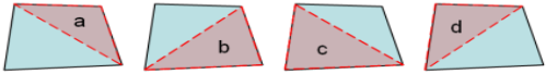 Figure 1. Example: Taper HyperMesh then finds the
smallest ratio of each of these triangular areas to ½ the
quad element’s total area (in Figure 1, "a" is smallest). The resulting value is
subtracted from 1, and the result reported as the element
taper. This means that as the taper approaches 0, the shape
approaches a rectangle.
Triangles are assigned a value of 0, in order to prevent HyperMesh from mistaking them for highly-tapered quadrilaterals and reporting them as "failed". |
| trias: min angle | Minimum allowable interior angle for a tria element. Any element for which any interior angle falls below the specified value is highlighted and remains highlighted until you exit the Check Elems panel or you select another check. |
| trias: max angle | Maximum allowable interior angle for a tria element. Any element for which any interior angle is greater than the specified value is highlighted and remains highlighted until you exit the Check Elems panel or you select another check. |
| quads: min angle | Minimum allowable interior angle for a quad element. Any element for which any interior angle falls below the specified value is highlighted and remains highlighted until you exit the Check Elems panel or you select another check. |
| quads: max angle | Maximum allowable interior angle for a quad element. Any element for which any interior angle is greater than the specified value is highlighted and remains highlighted until you exit the Check Elems panel or you select another check. |
3-d Subpanel
| Option | Action |
|---|---|
| warpage | The amount by which an element or element face (in the case of solid elements) deviates from being planar. Warpage of up to five degrees is generally acceptable. |
| aspect | The ratio of the longest edge of an element to its shortest edge. Aspect ratio should be less than 5:1 in most cases. |
| skew | Skew in trias is calculated by finding the minimum angle
between the vector from each node to the opposing mid-side and
the vector between the two adjacent mid-sides at each node of
the element. Ninety degrees minus the minimum angle found is
reported as the skew. Skew in quads is calculated by finding the minimum angle between two lines joining opposite mid-sides of the element. Ninety degrees minus the minimum angle found is reported. |
| tet collapse | Tetra elements whose collapse value falls below the value
specified are highlighted when the tetra collapse function is
selected. These elements remain highlighted until the Check
Elems panel is exited. Tetra collapse calculation: At each of the four nodes of the tetra, the distance from the node to the opposite side of the element is divided by the square root of the area of the opposite side. The minimum value found is normalized by dividing it by 1.24, and then reported. As the tetra collapses, this value approaches 0.0. For a perfect tetra, this value is 1.0. |
| cell squish | Non-orthogonality of an element with respect to its
faces.
|
| orthogonality | Checks normalized orthogonality for cells. Calculated as
minimum orthogonality within cell faces and across neighboring
cell faces:
|
| length > | The elements that have a length greater than the values specified are highlighted when the length function is selected. These elements remain highlighted until you exit the Check Elems panel or your select another check element function. |
| length < | The elements that have a length less than the values specified are highlighted when the length function is selected. These elements remain highlighted until you exit the Check Elems panel or your select another check element function. |
| jacobian | A measure of the deviation of an element from an ideally shaped element. The Jacobian value ranges from 0.0 to 1.0, where 1.0 represents a perfectly shaped element. However, Jacobian values of 0.7 and above are generally acceptable. The determinant of the Jacobian relates the local stretching of the parametric space required to fit it onto global coordinate space. HyperMesh evaluates the determinant of the Jacobian matrix at each of the element's integration points (also called Gauss points), and reports the ratio between the smallest and the largest. |
| equia skew | Opens the equiangle skew utility. This utility is used to find the number of elements among those displayed that have a normalized equiangle skew larger than the value specified. The normalized equiangle skew is defined as: |
| vol skew | Tetra elements whose volumetric skew measurement exceeds the
value specified are highlighted when the volumetric skew
function is selected. These elements remain highlighted until
the Check Elems panel is exited. Volumetric skew calculation: A sphere is fit through the four nodes of the tetra. That sphere defines an ideally shaped equilateral tetra, whose volume is . The actual volume of the tetra element is then calculated. The element's volumetric skew is then (Videal -Vactual)/Videal. This measure will, normally, equal the skew measure from Tgrid, and equal 1 minus the equivalent check in Abaqus. |
| vol AR | Elements whose Vol AR measurement exceeds the value specified
are highlighted when the Vol AR function is selected. These
elements remain highlighted until you exit the Check Elems
panel. Vol AR calculation for tetrahedral elements: The longest edge of the tetrahedron is found first, then the shortest altitude of the tetrahedron is found. The element's Vol AR, then, is the length of the longest edge divided by the length of the shortest altitude. For other types of 3D elements, the ratio of the longest to the shortest edge is reported. |
| tria faces: min angle | Minimum allowable interior angle for a tria element. Any element for which any interior angle falls below the specified value is highlighted and remains highlighted until you exit the Check Elems panel or you select another check. |
| tria faces: max angle | Maximum allowable interior angle for a tria element. Any element for which any interior angle is greater than the specified value is highlighted and remains highlighted until you exit the Check Elems panel or you select another check. |
| quad faces: min angle | Minimum allowable interior angle for a quad element. Any element for which any interior angle falls below the specified value is highlighted and remains highlighted until you exit the Check Elems panel or you select another check. |
| quad faces: max angle | Maximum allowable interior angle for a quad element. Any element for which any interior angle is greater than the specified value is highlighted and remains highlighted until you exit the Check Elems panel or you select another check. |
| neighbor size ratio | Checks volume ratio to find abrupt transitions in volume
mesh. Calculated as the ratio of minimum volume among a given
cell and neighboring cell to maximum volume among given cell and
neighboring cell. Ideal value depends on growth at which volume
mesh is growing. Values less than 0.2 may indicate an abrupt
transition. |
Time Subpanel
Use the time subpanel to determine the approximate minimum time step for explicit solvers based on element dimensions. Additionally, the added mass required to achieve the desired minimum time step can be displayed as a contour plot on the model.
| Option | Action |
|---|---|
| shells and solids, springs and beams, all types | Select the type of elements to check. Checks can be carried out separately for shell and solid elements, for spring and beam elements, or all element types. |
| display added mass | Plot a contour indicating the amount of required added mass
to achieve the minimum time step specified in the failure
criteria. To be used with the assign plot display plot. |
User Subpanel
| Option | Action |
|---|---|
| template | Select a template file. |
| filename | Select an output file. |
| all, displayed | Use this toggle to limit the check to those elements displayed on the screen, or all elements in the model. |
Command Buttons
| Button | Action |
|---|---|
| connectivity | Test the connectivity of a group of elements. 2D elements that share more than one edge (two connecting nodes form an edge of a first order element; two corner nodes and one mid-side node form an edge of a second order element) with another two-dimensional element are highlighted. 3D elements that share more than one face with another three-dimensional element are highlighted. Any elements where there are mid-side nodes connected to corner nodes are highlighted. This operator can be used to find duplicate elements. |
| duplicates | Check for duplicate elements. If an element is duplicated, the elements involved are highlighted, except for the element with the lowest ID. Duplicates can be deleted by clicking save failed and then retrieving the user mark (using extended entity selection) in the Delete panel. The saved (failed) elements can be accessed in any other panel using the retrieve option in the extended entity selection menu. |
| settings | Open the Check Element Settings dialog. |
| save failed | Save failed elements and replace them on the user
mark. When you use this function, elements that were previously on the user mark are replaced. Once the failed elements have been saved, the user mark can be loaded into other panels. The saved (failed) elements can be accessed in any other panel using the retrieve option in the extended entity selection menu. |
| standard, assign plot, histogram | Select a view mode, then click the green button for the
desired check to activate the view.
|
| execute | Run a check based on the template and filename specified. |
| preview unused | Locate and display all interface elements defined in the model that are not attached to any normal elements. |
| delete unused | Delete all interface elements defined in the model that are not attached to any normal elements. |
| reject | Undo the most recent deletion. |
| reset visual | Clear the histogram and return to the normal view of the model. |
| return | Exit the panel. |