Rotate Panel
Use the Rotate panel to rotate entities around an axis in space.
Location: Tool page
The axis of rotation can be selected in several different ways, and the entities rotated can include an entire model or only portions of it.
Do not use the Rotate panel to rotate a dummy. Doing so corrupts the tree structure and produces incorrect results when you reposition the dummy. Instead, use the Dummy panel.
To undo a rotation, rotate the entities in the opposite direction without changing the axis or angle: one click of rotate - undoes one click of rotate + and vice-versa.
Local coordinate system axes can be specified using the vector selection option.
When rotating components, all of the geometry (lines, surfaces, points) and elements (nodes) contained in the selected component are automatically rotated.
Rotating nodes or elements does not change connectivity or continuity of a mesh.
Rotating only some of the nodes in an element may distort the element.
Rotating surfaces may affect edge topology (shared edges may become free edges).
Rotating elements or surfaces independently will break any associations between the surfaces and the elements (nodes) created on them. Rotating in the opposite direction as described for "undoing" a rotation will not restore these associations. Lost associations can be restored via the Node Edit panel.
Panel Options
| Option | Action |
|---|---|
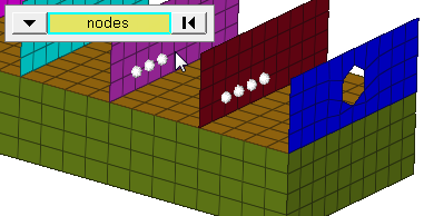
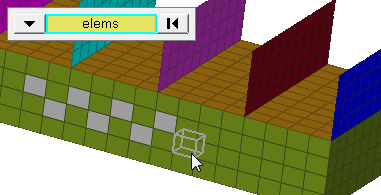
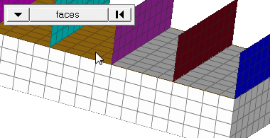
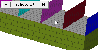
| entity selector | Select entities for
translation. When you select nodes or elems, click the
switch to change the selection mode.
|
| plane selector | Define the axis of
rotation.
|
| angle | Specify the number of degrees (positive or negative) that you want the selected entities to rotate each time you click rotate + or rotate -. Click this field twice to access the built-in calculator. |
| face angle / Individual selection |
|
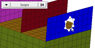
| edge angle |
Split edges that belong to a given face. When the edge
angle is 180 degrees, edges are the continuous boundaries of faces. For smaller
values, these same boundary edges are split wherever the angle between segments
exceeds the specified value. A segment is the edge of a single element.
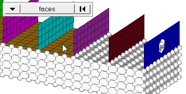
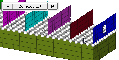
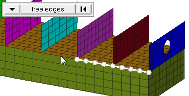
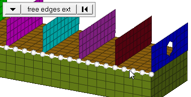
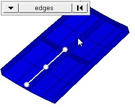
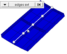
Important: Only available when the entity selector is set to nodes and the
selection mode is set to free edges, free edges ext, edges, or edges
ext.
|
Command Buttons
| Button | Action |
|---|---|
| rotate + | Rotate the selected entities in the positive direction of the rotation axis by the specified angle. Repeated clicks are cumulative. |
| rotate - | Rotate the selected entities in the negative direction of the rotation axis by the specified angle. Repeated clicks are cumulative. |
| return | Exit the panel. |