Weld Line Directions
Learn weld line direction conventions and how to rotate welds.
The weld line direction mainly defines the location of the evaluation points and the location of the weld line itself. For example, a T-weld could be connected from left to right or from right to left.
If you consider a coordinate system to represent the direction of the weld line:
- The Y axis of the coordinate system points to the first evaluation point, and is perpendicular to the weld line.
- The Z axis, in case of T and L welds, points towards the web material.
- The X axis represents the direction of the weld line.
T, L, X, and M Welds
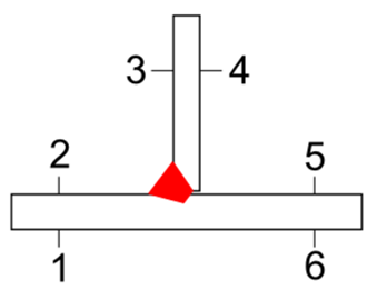
Figure 1.
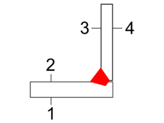
Figure 2.
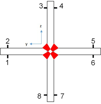
Figure 3.
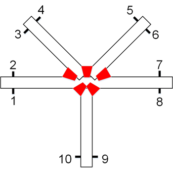
Figure 4.
For these weld types, the three nodes to be selected are:
- The first node should be perpendicular to the weld line, and lie on the base material. This will be the Y axis of the coordinate system.
- The second node should lie on the weld line. This will be the origin of the coordinate system.
- The third node should also be perpendicular to the weld line and lie on the web material. This will be the Z axis of the coordinate system.
Butt and Overlap Welds
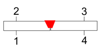
Figure 5.
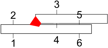
Figure 6.
For these weld types, the three nodes to be selected are:
- The first node should be perpendicular to the weld line and lie on the first base material. This will be the Y axis of the coordinate system.
- The second node should lie on the weld line. This will be the origin of the coordinate system.
As part of the pre-processing steps, the following checks should be done before
starting the weld evaluation process:
- Check if the weld lines identified by the tool are actually weld interfaces.
- Check if the weld lines are organized into meaningful components. There can be cases that the welds may be split into two or more weld lines when it should have been a single weld line.
- Check if the location of the weld line is correct.
Change Weld Line Directions
Rotate welds about the Y or Z axis.
From the weld line browser, right-click on a weld line, then select Rotate Y or
Rotate Z and a rotating option.
| Option | Description |
|---|---|
| All | Rotate the corresponding axis of the entire weld. |
| Weld Elements | Rotate the corresponding axis of selected weld segments using the
guide bar.
Tip:
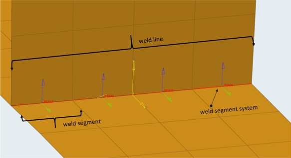 Figure 7. |