Prepare Modules
In a real-life application, necessary preparation work needs to be done to get the module representation files to a state that is ready for assembly. Use the Prepare Module tool to accomplish this goal.
In Prepare Module mode, the HyperMesh database is first cleared to remove any potentially conflicting FE entities and then the root representation file is loaded into HyperMesh. A module ID summary is presented with all necessary information needed for you to determine if the IDs need to be renumbered and what range they should be renumbered to.
- Add spider
- Add spiders to a round hole. Select a type, DOFs and pick center (RBE3 only) and edge nodes, then click Create.
- Add PLOTEL
- Helps you with PLOTEL display elements.
- Edit systems
- Relocate or orient the module by modifying the reference local coordinate system. This option takes you directly to the System panel to edit existing systems.
- Orient and position
- Help translate and rotate FE entities. Input values in the appropriate fields.
- Edit materials
- Help fill the RHO (Density) and GE (Damping) field of MAT1 cards. Enter a density and/or damping value in the input box and click All or Select to apply the values to all or selected material cards.
- Initialize stamping effect
- Helps generate stamping effect on sheet metal panel thickness for FE representation includes.
- Composite Response
- Helps define a new response point by relating its motion to existing tagpoints in the model. The most common example is to define a steering wheel nibble response using tagpoints at 6 o’clock and 12 o’clock on the steering wheel.
In addition, a number of functionalities on the Tagpoints tab of the Edit Module, such as Add, Assign and Generate PLOTEL elements are enabled for you to manually add tagpoints and assign them to grids in the module.
A Tagpoint Mapping tool is also available in the Prepare Module tab via the ![]() icon. The mapping tool is
able to reconcile in bulk the current tagpoint definition in the assembly database with what
is in the root module file. You can also create new tagpoints by reading a
.csv file that contains hard point coordinate and label
information.
icon. The mapping tool is
able to reconcile in bulk the current tagpoint definition in the assembly database with what
is in the root module file. You can also create new tagpoints by reading a
.csv file that contains hard point coordinate and label
information.
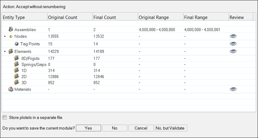
Figure 1.
- Yes
- The root representation file is to be saved, in this case, intra and inter ID conflict flag will be set to Yes.
- No
- The root representation file is not to be saved, in this case, intra and inter ID conflict flag will be set to No.
- Cancel
- The exit Prepare Module Mode action is aborted.
- No, but VALIDATE
- In this case there is no change to the file and no need to save the file, but intra and inter ID conflict flag will be set to Yes.
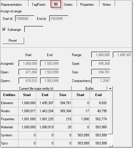
Figure 2.
Mass Extraction Utility
- Extract module mass, moment of inertia and center of gravity information in prepare module mode.
- Automate the creation of rigid body representation for the module using the above information.
- Calculate the information by clicking Calculate. This will calculate the mass information necessary for rigid body representation of a module.
- Clicking Scan .OUT scans the information from the .OUT file. This will scan the mass information from the .OUT file generated using MASSPROP during the solver run.
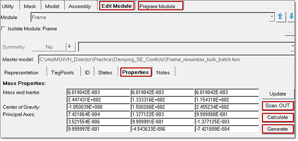
Figure 3.
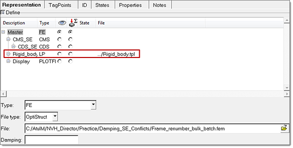
Figure 4.