Connection Manager
Connections can be managed by right-clicking on a connector in the Connector Browser and selecting Edit Connection.
Managing Connections
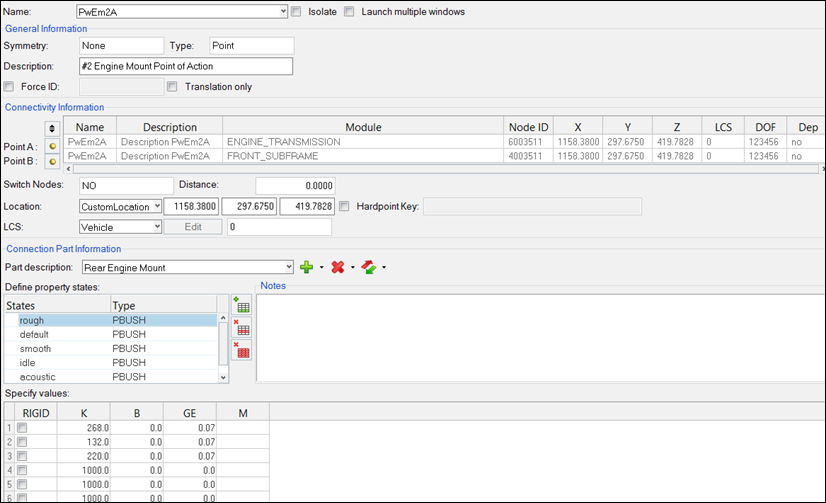
Figure 1.
The Generation Information section has the information on symmetry, connection type, connection description and Force ID. Force ID for connectors gives you an option to define the numbering pattern to a connector, so that the connection elements created by realization of those connectors fall in the defined numbering pattern.
The Connectivity Information section has information related to Connected Points, Switch Nodes status, and distance between them. A connection location type can be defined by selecting one of the options from the pull down menu: Point A, Point B, Midpoint, or a Custom Location. When a Custom Location is selected, the location can be defined either by specifying particular coordinates, or by mapping it to a Hardpoint Location.
- Vehicle
- ‘0’ or the basic coordinate system is used.
- Owned
- This option allows you to create a custom LCS by clicking Edit.
- TagPointA
- Local coordinate system specified as the output Displacement Coordinate System on the grid card associated when TagPointA is used.
- TagPointB
- Local coordinate system specified as the output Displacement Coordinate System on the grid card associated when TagPointB is used.
- Axis-Plane
- Two vectors are required to define this system. A vector can either be specified in direction cosines, or by selecting two tagpoints.
- Angle
- Any combinations of angle rotations around the reference axes can be used to define this system.
- Ujoint
- The Ujoint coordinate systems is defined by selecting two tagpoints on the input shaft and two tagpoints on the output shaft. A homo-kenetic coordinate system will then be created to properly describe motion transfer of Ujoints from the input to the output shafts.
-
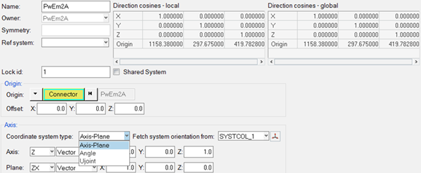
Figure 2.
Connection Part Information allows an efficient way to create and assign connection parts to connections. New connection parts can be created by copying the existing connection parts. Connection part from the available parts list is assigned to a connection in the property view tab of the Connection browser. There is also an option to import and export property .csv file from the edit connection GUI in the Connection browser.
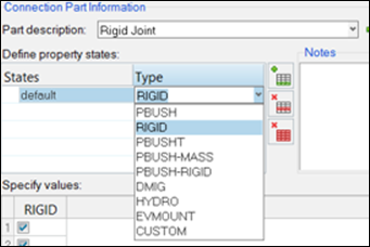
Figure 3.
- PBUSH
- A CBUSH element is generated during connection realization. The PBUSH card allows you to specify K (stiffness), B (viscous damping), GE (material damping), M (mass and moment of Inertia) and RIGID (check boxes for rigidly connected DOFs.) Note: The M and RIGID fields are not supported in the Nastran profile and are ignored.
- RIGID
- A RBE2 element with DOFs specified in checked boxes is generated during connection realization.
- PBUSHT
- A CBUSH element is generated during connection realization. In addition to the PBUSH card that specifies the base properties, a PBUSHT card allows you to specify frequency tables for K, B and GE.
- PBUSH-MASS
- A CBUSH element with two COMN2 elements at its Point A and Point B are generated during connection realization. Note: This type is designed to be used in the Nastran profile where the M fields for PBUSH are not supported by the Nastran solver.
- PBUSH-RIGID
- A CBUSH element with a parallel RBE2 element are generated during connection realization. Note: This type is designed to be used in the Nastran profile where the RIGID check boxes for PBUSH are not supported by the Nastran solver.
- DMIG
- Direct Input Matrix
-
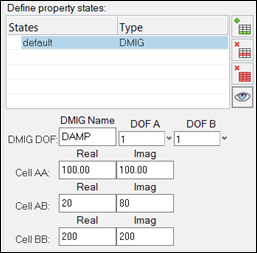
Figure 4. - HYDRO
- Hyrdostatic Mount
-
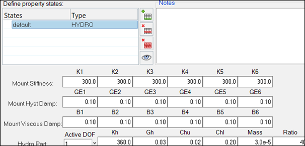
Figure 5. - EVMOUNT
- Electric motor mount with mass at the center of elastic part.
-
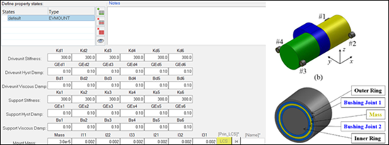
Figure 6. - CUSTOM
- Custom properties using custom scripts.