Connection Browser
Once the connections have been created, use the Connector Browser to review the connections.
Reviewing Connections
The Connector Browser is divided into two browser panes. The top pane is the Module Pane, where connected modules are listed. You can view connections attaching to modules using typical browser functions, such as Show/Hide/Isolate. The lower pane is the Connector Pane, where individual connections are listed.
The following connection views are available from the Connector Pane.
-
- Connectivity View

-

Figure 1.- PointA/PointB
- These two columns show the two tagpoints on two modules that are being connected for each connection. The same order (PointA first and PointB second) is used when generating connection FE entities during connector realization. PointA/PointB may be shown with two incomplete status indications (in square brackets): [N/A] indicates that the tagpoint exists in the assembly database, but is not available in the HyperMesh session (not imported.) [Undefined] indicates that the tagpoint does not exist in the current assembly database, which means the tagpoint is either deleted or the sub .xml file it travels with is not imported in the session.
- Owning Module
- This column indicates which module owns the particular connection. The owning module is always the module on the PointA side of the connection. The connection definition and properties always travel with or organized under their owning modules when sub .xml files are written.
- Distance
- This column shows the distance between PointA and PointB. It can be used as a metric for checking the validity of the connection. Connections spanning large distances are potentially connected by mistake. Some NVH engineers prefer to keep all connections at zero length due to fear that non-zero length springs may introduce unintended dynamic motion, which is a valid concern if celas type spring elements are used during connector realization. When cbush type spring and rbe2 type rigid elements are used, this is the case for all current NVH Director supported realization types, correct dynamic motion is ensured by element formulation and there is no longer a need to maintain zero connection length.
- Switch Nodes
- This column shows if there is a need to switch the order by which PointA
and PointB are used in generating rbe2 rigid elements during connector
realization. This need is driven solely by dependency considerations of the
connected points, since a point that is already dependent cannot be made the
dependent point again in the connection element definition. Four possible
states of this column are possible.
- No
- If PointA is independent, regardless of the dependency of PointB.
- Yes
- If PointA is dependent, but PointB is independent, in which case PointB will be made the independent point in realizations involving rbe2.
- Unresolvable
- This happens when both PointA and PointB are already dependent, in which case a realization involving rbe2 is not possible and the connection will fail to realize.
- Unknown
- If PointA’s dependency status is unknown or if PointA is dependent and PointB’s dependency status is unknown.
- Forced ID
- Force ID's for connectors gives you an option to define the numbering pattern to a connector, so that the connection elements created by realization of those connectors fall in the defined numbering pattern.
-
- Property View

-
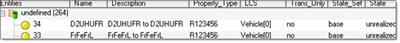
Figure 2.
-
- Location View

-
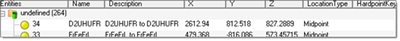
Figure 3.