Transceiver Configuration
Specify the parameters of the transceiver.
Parameters of a transceiver can be specified on the Transceiver Configuration dialog.
Figure 1. The Transceiver Configuration dialog.
- General
-
- Enabled
- Option to enable/disable transceiver. If the transceiver is disabled, it
will be excluded from all computations and displayed with grey
color.Note: Disabled transceivers can be hidden in the 2D View and 3D View by pressing Ctrl + F1.
- Name
- Arbitrary name of transceiver.
- ID
- Unique ID of transceiver (can not be changed).
- Channel ID
- ID of radio channel that is used for communication.
- Downlink Frequency
- Center frequency of the downlink channel. This is just for information. The frequency can be changed by selecting another channel via channel ID.
- Transmitter
-
- Power
- Transmit power of transceiver.
- Fast Fading Margin
- The parameter Fast Fading Margin represents the difference (in dB) between the maximum possible transmit power and the maximum allowed transmit power. In order to ensure fast power control to compensate for the deep fades of the radio channel this specific headroom is required. Appropriate values for this headroom have to be determined via link level simulations and will depend on the mobile speed.
- Accumulated Transmission Time
- Accumulated time of transmission for determination of overflows.
- Measurement
- Optionally measurement data can be assigned to the transmitter in order to calibrate the wave propagation model.
- Min. Required SNIR
- Minimum signal-to-noise-and-interference-ratio which is required to receive the signals.
- Receiver
-
- Noise Figure
- Defines additional noise generated by the receiver.
- Min. required signal level
- Minimum signal level required for reception.
- Antenna
-
- Type
- Omni directional (isotropic) or directional antenna.
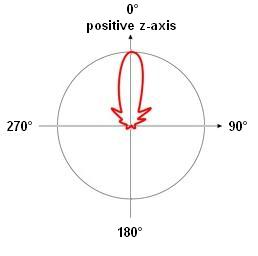
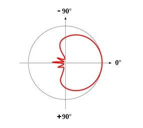
- Orientation
- Azimuth and tilt adjustment of the antenna element. The azimuth angle is defined north over east, thus north direction corresponds to zero degree, east direction corresponds to 90 degree. A down tilts can be specified using a positive number, an up tilt is defined with a negative number.
- Pattern
- File path and name of the antenna pattern to be considered.
Figure 2. The Transceiver Measurement Data dialog.
- Measurement File
- Measurement data which shall be assigned to the current transceiver.
- Calibration File
- File path and name of the resulting calibration file. The calibration file will be created during the wave propagation prediction and can be used to calibrate the wave propagation model.
- Usage Mode
- The assigned measurement data can be either used for Area Prediction or Point-To-Point (Node Prediction). If measurement data shall not be used at the moment, Inactive has to be selected.
| Azimuth adjustment | Tilt adjustment |
|---|---|
 |
 |