Use the Midmesh Panel to automatically generate a mesh at the midplane location,
directly from the input geometry (components, elements, solids or surfaces), without first
creating a midsurface.
Create Subpanel
Use the Create subpanel to control the resulting midmesh output.
entity selector
Select the source used to create the midmesh.
Destination component
Select which component newly created midmeshes are placed in.
Ignore flat edges
Do not imprint flat edges from the input geometry onto the
midmesh.
Figure 1. Option Off
Figure 2. Option On
Flatten connections
Aligns/flattens the midmesh at ribs/connections.
Figure 3. Option Off
Figure 4. Option On
Step offset mode
This option allows finer control of how stepped geometry (one side
continuous surface, and opposite side steps) is captured. This option is
valid only when flatten connections is enabled. Values can be:
Automatic – Steps of different thickness across a
common base surface are automatically offset to a uniform distance from
the base surface.
Middle everywhere – Each step will be placed in
the middle everywhere.
Middle of thickest plate – All steps that share a
common base are moved to the middle of the thickest step. This might
place portions of the midmesh outside the solid.
Middle of thinnest plate – All steps that share a
common base are moved to the middle of the thinnest step.Figure 5.
Edit criteria
Set the minimum size and target element size settings in the criteria
file to control the resulting midmesh via the Criteria File Editor.
Extraction size
The midmesh extraction size. By default, this is taken as the target
element size from the criteria file. This can be set smaller than the
target size, though that is not recommended unless there are problems
extracting at the target size.
Minimum size
Minimum element size allowed in the finalized mesh. This in combination
with the ‘suppress proximity edges factor’ and 'combine non-manifold
edges factor’ can ensure that the output mesh is ready for rebuild with
the same criteria.
Can only be modified in the Criteria File
Editor.
Suppress proximity edges factor
The minimum size factor for removing edges within proximity. Edges
closer than this factor times minimum size will be
suppressed.
Figure 6. Option Off
Figure 7. Option On
Combine non-manifold edges factor
The minimum size factor for joining non-manifold edges. Non-manifold
edges closer than this factor times minimum size will be
combined.
Figure 8. Option Off
Figure 9. Option On
Defeature ribs width factor
The minimum size factor for removing small ribs. Ribs closer than this
factor times minimum size will be suppressed. Default is 0.9.
Defeature openings with width <
The maximum width for removal of small holes and openings.
Use the Edit Face subpanel to correct issues with midmesh faces.
fill face
Create a mesh within a closed 1D topology loop, attempting to keep
tangency. Optionally, the 1D loop can be deleted, keeping only free and
non-manifold edges.
Figure 29. Before
Figure 30. After
repair face
Attempt to fix topological problems (holes/gaps/cracks, intersections,
slivers, overlaps) in the mesh and remesh the face.
Figure 31. Before
Figure 32. After
detect intersections
Detect intersecting element clusters and holes/gaps/cracks, and create
element sets for further handling.
Figure 33. Before
Figure 34. After
align face
Align a selection of elements to an input geometry surface:
Figure 35. Before
Figure 36. After
An optional offset can be specified to align the mesh at a given
distance away from the surface:Figure 37. Offset
Optional locking of boundary nodes of the selection will treat them as
anchors:Figure 38. Lock
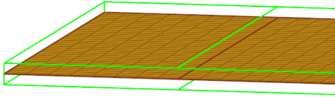
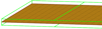
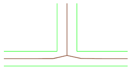
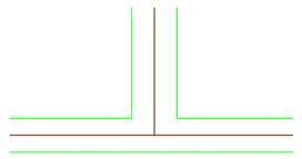
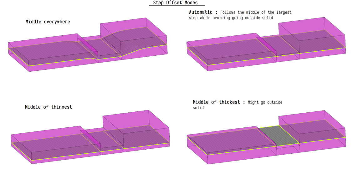
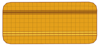
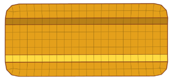
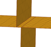
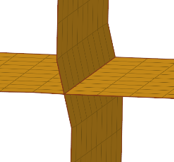
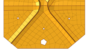
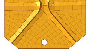
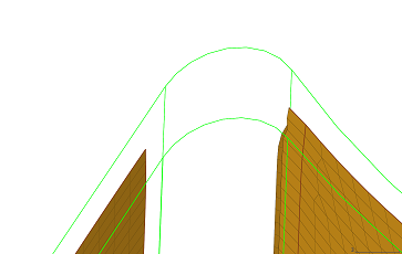 Figure 12. Before
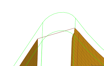 Figure 13. Without Guides
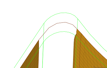 Figure 14. With Guides
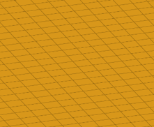
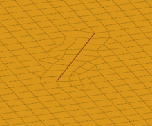
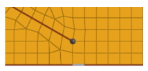
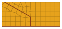
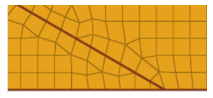
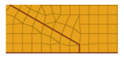 Figure 20. Mixed Path
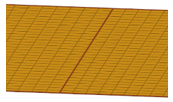
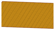

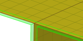
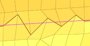
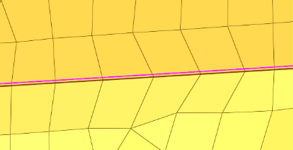
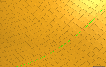 Figure 27. Imprint Before
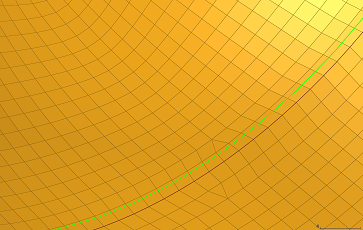 Figure 28. Imprint After
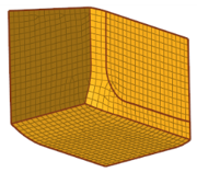
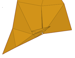
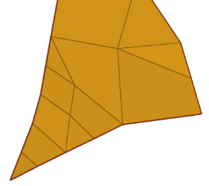
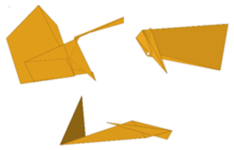
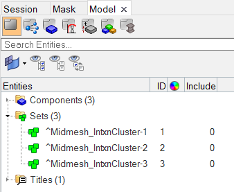 Figure 34. After
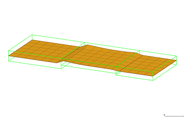 Figure 35. Before
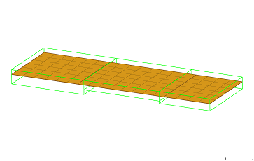 Figure 36. After
 Figure 37. Offset
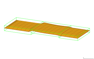 Figure 38. Lock