Use the Replace panel to relocate one node to the position of another or manually
equivalence two nodes.
Location: 1D, 2D, 3D pages
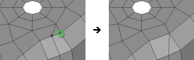
In Figure 1, the dark gray node
is replaced by the node highlighted by the green circle. The tria above the two
selected nodes is destroyed, and the quad below them converts to a tria. Figure 1.
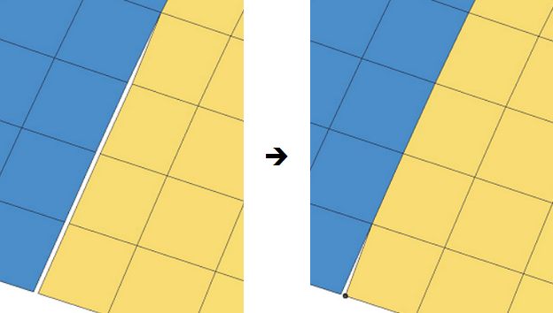
In Figure 2,
the replace node function is used to close a discontinuity in the mesh. The gap
shown in the left image is closed by replacing a node of the yellow element with a
node of the blue element. The equivalence option will redefine the yellow element to
use the same node ID as the blue element so element connectivity is ensured. Figure 2.
Replacements occur immediately upon selecting the nodes; there is no command button
to trigger the replacement, only to reject (undo) it. The replacement is made
permanent when you leave the panel or combine another node pair, therefore you
cannot reject it after leaving the panel and returning.
When a node replacement is going to destroy an element, a will receive a warning
message. Proceed according to your needs.
Yes
Replace the node and destroy the element.
No
Abort the replacement.
yes to All
Automatically accept the current replacement and all subsequent
replacements, suppressing the warning message until you exit and
re-enter the panel.
no to All
Automatically abort the current replacement and any subsequent
replacements that would result in a destroyed element, suppressing the
warning message until you exit and re-enter the panel.
Panel Options
Option
Action
replace: node
Select a node to
relocate to location of the second node.
with: node
Select a node to
retain. Depending on the settings, it may or may not remain in
its original location.
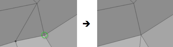
equivalence
Redefine any entities
referencing the first node, to replace that reference with the
node ID of the second node. Figure 3.
Clear the equivalence checkbox to relocate the replaced
node to the location of the retained node. Both nodes will
remain as distinct, coincident entities. In Figure 3, this would cause the tria element to become a
sliver.
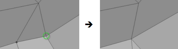
at mid-point
Combine the two nodes
at the midpoint between their original locations. Affected
elements may be destroyed or changed. Figure 4.
total =
The total distance
between the original replace node and with node. This is a
read-only field (you cannot change the values) that populates
when the replacement occurs.
x dist =
The global X component
between the original replace node and with node. This is a
read-only field (you cannot change the values) that populates
when the replacement occurs.
y dist =
The global Y component
between the original replace node and with node. This is a
read-only field (you cannot change the values) that populates
when the replacement occurs.
z dist =
The global Z component
between the original replace node and with node. This is a
read-only field (you cannot change the values) that populates
when the replacement occurs.