Velocities Panel
Use the Velocities panel to create concentrated velocities.
Location: Analysis page
Concentrated velocities are created by applying a load, representing velocities, to a node.
Velocities are load config 8 and are displayed as a vector with the letter V at the tail end.
Create Subpanel
| Option | Action |
|---|---|
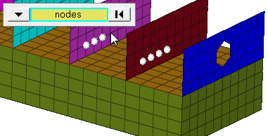
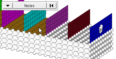
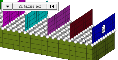
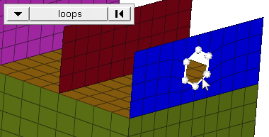
| entity selector | Select the entities to
which the velocity will be applied. In any case, the velocities are applied to nodes; this selection simply determines how those nodes are selected. Geometric points select the nodes at which they exist. Comps select all of the nodes contained within the chosen component. If you choose comps or sets, HyperMesh draws the velocities using a single indicator. As a result, a new button called display appears. This allows you to indicate where in the model you wish the indicator to be drawn, and requires additional steps. When nodes is selected, use the switch to
change the selection mode.
|
| global system / local | Specify the method of determining the velocity's magnitude. |
| magnitude = | Specify the method of
determining the velocity's magnitude.
|
| relative size / uniform size |
By default, loads are displayed relative to the model
size.
|
| label loads | Display the load's text labels in modeling window. |
| face angle / individual selection |
|
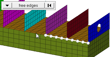
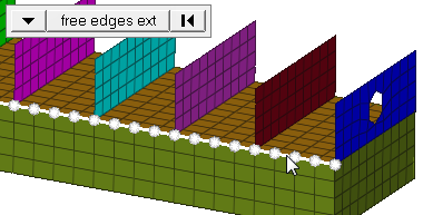
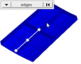
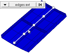
| edge angle |
Split edges that belong to a given face. When the edge
angle is 180 degrees, edges are the continuous boundaries of faces. For smaller
values, these same boundary edges are split wherever the angle between segments
exceeds the specified value. A segment is the edge of a single element.
Important: Only available when the entity selector is set to nodes and the
selection mode is set to free edges, free edges ext, edges, or edges
ext.
|
Update Subpanel
| Input | Action |
|---|---|
| entity selector | Select the entities to
which the velocity will be applied. In any case, the velocities are applied to nodes; this selection simply determines how those nodes are selected. Geometric points select the nodes at which they exist. Comps select all of the nodes contained within the chosen component. If you choose comps or sets, HyperMesh draws the velocities using a single indicator. As a result, a new button called display appears. This allows you to indicate where in the model you wish the indicator to be drawn, and requires additional steps. When nodes is selected, use the switch to
change the selection mode.
|
| global system / local | Specify the method of determining the velocity's magnitude. |
| magnitude = | Specify the method of
determining the velocity's magnitude.
|
| relative size / uniform size |
By default, loads are displayed relative to the model
size.
|
| label loads | Display the load's text labels in modeling window. |