Calculate and Assign Midmesh Thicknesses
Calculate and assign the thickness of a midmesh from solid geometry using the Midmesh Thickness tool.
Select Midmesh and Solid Inputs
The midmesh and solid can be specified by manually selecting entities from the current HyperMesh session, or by selecting external geometry or FE solver decks as input.
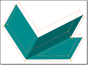
Figure 1. FE and Geometry with Traditional Element Visualization
| To select input from | Do this |
|---|---|
| External geometry/FE solver decks |
|
| Existing entities |
|
Define Thickness Output
Calculate and assign a thickness on the midmesh.
-
Define thickness options.
Option Action Minimum thickness/Maximum thickness Define a thickness to assign calculated thicknesses. - To enter a minimum thickness to assign calculated thicknesses below a specified value, select the Minimum thickness checkbox.
- To enter a maximum thickness to assign calculated thicknesses above a specified value, select the Maximum thickness checkbox.
Assign offset to elements/sections To assign an offset value to elements if they are not in the middle of the selected geometry, select the Assign offset to elements/sections checkbox. 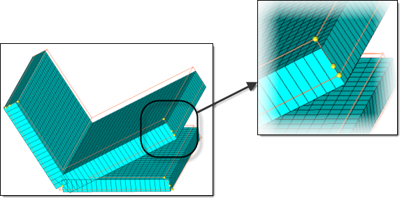
Figure 2. 2D Detailed Element Representation On, No Element Offset On. The mesh deviates from the geometry; the midmesh node is equidistant from mesh corners, but not from the nodes on the geometry corners.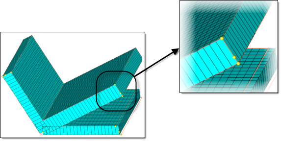
Figure 3. 2D Detailed Element Representation On, Element Offset On. Offset has caused the mesh to match the geometry, though the initial midmesh node remains unchanged, such that it now matches the geometry.Assign average thickness to element groups To approximate the thickness values on individual elements to be an average value representing a group of elements, select the Assign average thickness to element groups checkbox. Note:Only available when Thickness output is set to Elements.
Consider a model which has a thickness variation as shown in Figure 4. If you assign thickness on elements, by default you will get a highly variable distribution.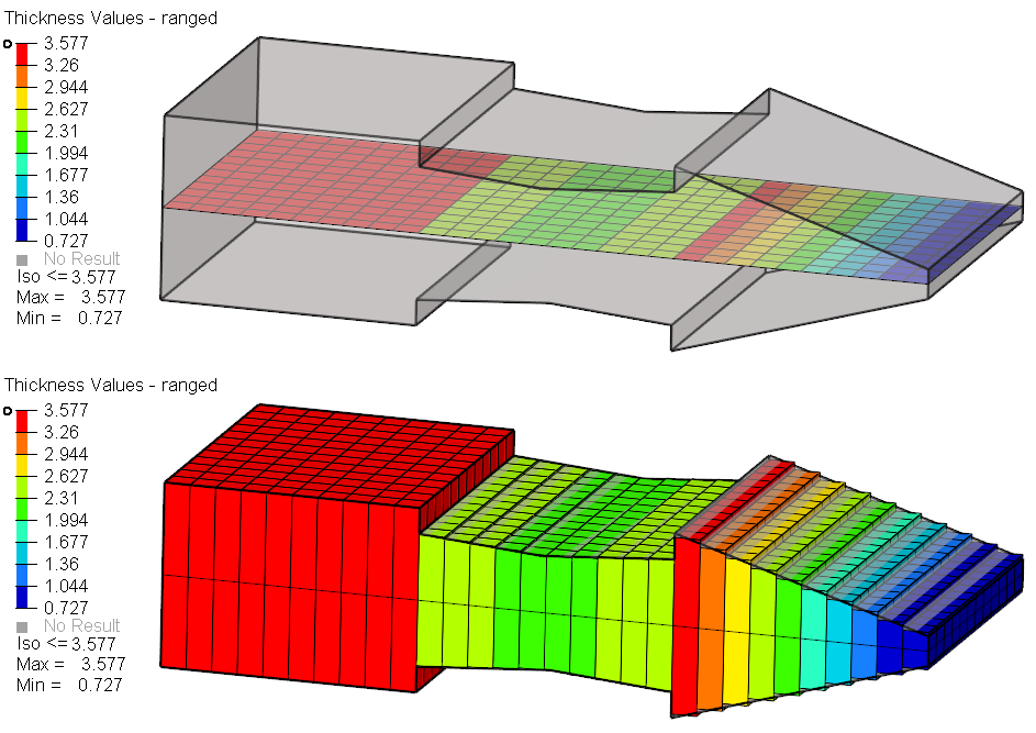
Figure 4.Each row of elements is assigned a different thickness, resulting in various thicknesses, even if the solid was captured accurately.
Enabling Assign average thickness to element groups groups elements with similar thicknesses together, and assigns an average thickness to the groups. In Figure 5, the middle region of the model is assigned a single thickness and the right section is assigned fewer steps. The accuracy of the model captured is reduced.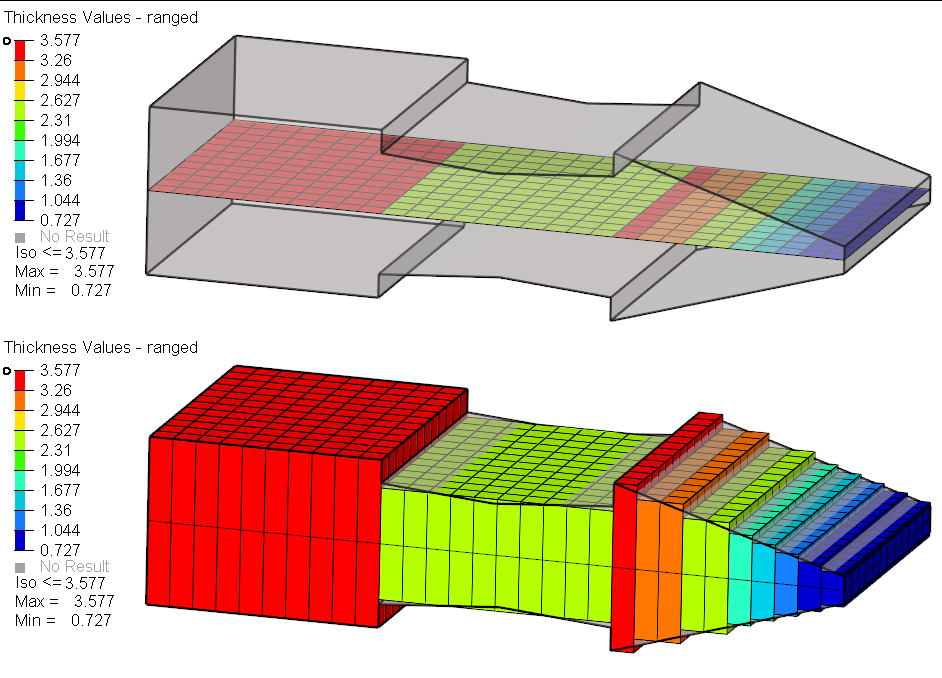
Figure 5.Note: This is the default behavior if the Thickness output option is set to Properties on elements or Properties on components.Maximum thickness range interval Control how similar thickness elements are grouped together. - Choose Rel (relative interval value) to
specify a relative interval value, which defines the relative
width of each thickness band.
For example, suppose you enter a Rel value of 0.2. Starting from the element with the smallest thickness, elements with similar thickness are grouped together, such that the difference between maximum and minimum thickness in one group does not exceed 0.2 times the maximum thickness in the group. The thickness values of elements in a group is averaged and assigned to all of the elements in the group (or to the property.)
- Choose Abs (absolute interval value) to
specify a value to use as the cut off for the maximum range of
the thickness in a group.
If this value is 0.5, the difference between maximum and minimum of the thickness values in a group / property will be a maximum of 0.5.
Smaller values result in a larger number of properties that will be created, allowing the thickness variation to be captured more accurately.
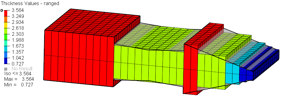
Figure 6. . Assign average thickness to element groups: On / Maximum thickness range interval: Rel = 0.5.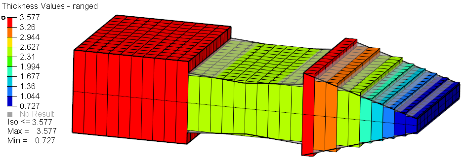
Figure 7. . Assign average thickness to element groups: On / Maximum thickness range interval: Rel = 0.2.Note: Available when Assign average thickness to element groups is enabled, or if thickness output is set to Properties on Elements or Properties on Components.Fixed interval with start thickness Control thickness properties at constant intervals. Enter a desired thickness value in the Start thickness field, and a thickness interval value in the Interval field. All elements will be grouped into properties/components with fixed increments to the thickness specified by the interval value, beginning with the start thickness value.
Truncate thickness to range interval Round the thickness values up or down to have the same number of decimal digits as the input value in the Maximum thickness range interval field.. There are three modes available. Automatic determines an optimal truncation.
-
Define advanced options.
Option Action Correction method Select a correction method to perform on elements or nodes where the thickness could not be computed correctly. - Choose Interpolate from Neighbors to interpolate an appropriate thickness value from the neighboring element/node thickness.
- Choose Adjust to min/max values to assign either minimum or maximum thickness, if they are defined, to the corrected elements.
Scaling at corners [0,10] Enter a scaling factor to use when interpolating thickness values near t-junctions or corners. A value less than 1 will result in linear decrease in the thickness values nearer to the junction/corners. A value of zero will result in an approximate mass-conserved thickness estimation. When equal to 1, the thickness is extrapolated / interpolated without any scaling. When greater than 1, the thickness will increase as you go closer to the junction.
Only available when the Correction method is set to Interpolate from Neighbors.
Figure 8. Scaling at corners = 0, Thickness Contour Applied, Traditional Element Visualization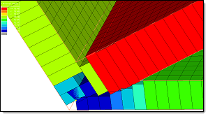
Figure 9. Scaling at corners = 0, Thickness Contour Applied, 2D Detailed Element Representation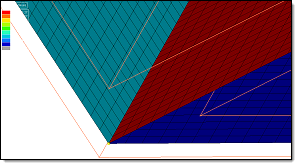
Figure 10. Scaling at corners = 1, Thickness Contour Applied, Traditional Element Visualization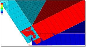
Figure 11. Scaling at corners = 1, Thickness Contour Applied, 2D Detailed Element RepresentationMax midmesh / solid angle [0.1,90] Enter the cut-off angle in degrees. Enter the maximum angle (0 to 90) that the mid-mesh makes with the solid, beyond which the estimated thickness will be ignored and corrected.
For example, the images below show the midmesh in blue, and the solid in black. In the first image the midmesh and the solid form a moderate angle. However in the second image the midmesh and the solid form a larger angle. It is possible that this area is a junction, located at the solid edge, or the solid may contain some noisy features, therefore you may want to ignore the calculated thickness and interpolate that value from surroundings.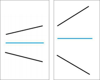
Figure 12.Max thickness gradient [0, 10] Measures the change in adjacent thickness values, and restricts the gradient.
Enter the maximum change in thickness allowed across two adjacent measurement locations, as a factor of the distance between the locations. Allowable factors range from 0 to 10.
For example, the image below shows a tiny projected boss in an otherwise planar area, which you may want to ignore. Defining the Max thickness gradient specifies the cut-off for the ratio of difference in thickness at two locations to the distance between the two locations. If the ratio is more than the given value, the measured thickness is discarded, and interpolated from its neighbors.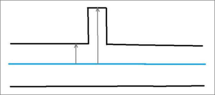
Figure 13.Max relative faceting error Enter a maximum relative faceting error to use during faceting calculations. When HyperMesh computes the proximity with a solid, it does not actually compute with the surface geometry. Instead, HyperMesh computes with the tessellated approximation (facets) of the geometry. In case of curved geometry, the facets may not exactly match the geometry, and hence the thickness is computed, causing faceting errors. Specifying the Max relative faceting error enables you to control the accuracy of the tessellation used, as a factor of the estimated thickness. The Max relative faceting error is the ratio of the maximum error of facets to the estimated thickness. If it exceeds this value, facets are further refined to better capture the geometry.
Max search distance Enter the maximum distance which will be considered for searching solid proximity. This value is also used to restrict the maximum distance from which a good thickness value is considered for correcting an incorrect thickness estimate. You can also used this option to restrict the algorithm from assigning incorrect thicknesses for the mid-mesh that is out of the solid proximity. Do not assign thickness to midmesh outside solid Do not assign a thickness to the midmesh outside of the solid.
Define Visualization Settings
Define visualization settings for the midmesh.
| Option | Action |
|---|---|
| Element coloring by thickness | Set the Element Color mode to By
Thickness resulting in a contour plot of thickness.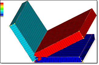 Figure 14. Thickness Contour Applied, 2D Detailed Element Representation |
| 2D detailed element representation | Display midmesh elements as 2D with the assigned thickness as
depth.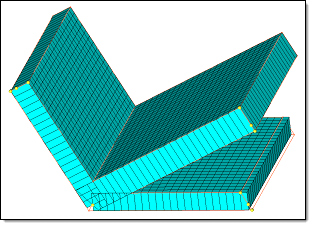 Figure 15. 2D Detailed Element Representation The behavior of 2D Detailed Element
Representation depends on what you assigned a thickness to. For
example, if you assign a component an element thickness, then the
element thickness representation will be displayed. If you assign a
nodal thickness to an element node, then each individual node
thickness will be plotted and you will be able to see the first and
second order trias and quad elements. When you assign a nodal
thickness, you can select the By Thickness
option in the Visualization toolbar to display each node value. If
you assign a nodal thickness, and offset is on, then the element
thickness from the nodes will be calculated, the element will be
offset, and the nodal thickness 2D Detailed Element representation
on the offset elements will be plotted.
Restriction: Composites with variable thickness are not added for this
feature.
|
| Highlight corrected elements | Highlight the elements whereby the thickness could not be calculated
from solid, and deploy the correction method.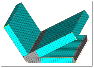 Figure 16. 2D Detailed Element Representation, Corrected Elements Highlighted |
Midmesh Thickness Assignment Behaviors
Common and solver interface specific behavior for assigning thicknesses to the midmesh.
Abaqus
- Nodes
-
- Creates a single node set named HM_NodalThickness with a Nodal_Thickness card image.
- You need to create a property and assign it to the selected 2D elements.
- Adds the relevant nodes to the node set.
- Assigns a single thickness to each node using the attribute ThicknessValue.
- Elements
-
- Creates a single table named HM_ElementThicknesss with a Nodal_Thickness card image Distribution_Table.
- You need to create a property and assign it to the selected 2D elements.
- Assigns a single thickness to each element using the attribute ThicknessValue.
- Properties on elements
-
- Based on the thickness, multiple properties with either SHELLSECTION or SHELLGENRALSECT card images are created.
- Creates corresponding materials and properties named
thickness_t.Note: During creation, you are able to enter a name for the property and material.
- Assigns a property to the selected 2D elements.
- Properties on components
-
- All the options mentioned above, are applicable for Properties on components, except the properties are assigned to components instead of elements.
ANSYS
- Properties on components
-
- Based on the thickness, multiple properties/sections with the REAL SET or SECTYPE card images are created.
- Creates corresponding properties/sections named thickness_t.
Note: During creation, you are able to enter a prefix for the property/section.
- Assigns a property to the components.
LS-DYNA
- Nodal Thickness onn Elements
-
- If you select Nodal thickness on elements, a thickness is assigned to each node on corresponding elements. A thickness will be assigned to nodes that have the following THIC attributes of the *ELEMENT_SHELL_THICKNESS card: THIC1, THIC2, THIC3 and THIC4.
- Elements
-
- If you select Elements, a thickness is
assigned to the THIC1, THIC2, THIC3, and THIC4 fields of the
card *ELEMENT_SHELL_THICKNESS. A single value thickness will be
assigned to all of the thickness attributes of the
element.Note: If the element is of type TRIA, then a THIC3 thickness will be assigned to THIC4. If you change the view to 2D Detailed Element Representation from the Visualization toolbar, then THIC4 will be ignored for TRIA elements.
- If you select Elements, a thickness is
assigned to the THIC1, THIC2, THIC3, and THIC4 fields of the
card *ELEMENT_SHELL_THICKNESS. A single value thickness will be
assigned to all of the thickness attributes of the
element.
- Properties on Components
-
- Based on the thickness, multiple properties with SHELLSECTION card images are created.
- Creates corresponding materials and components named
thickness_t.Note: During creation, you are able to enter a name for the property and component.
- Assign a property to the components that were created.
- Write INCLUDE_STAMPED_PART
-
- If you select this checkbox, an include file is created for each
component selected for the run. A system collector is also
created with the card image includeStampedPart, and associate it
to the created include file.Note: Only valid for the Thickness output options Elements and Nodal thickness on elements. It is not supported for Properties on Components.
- If you select this checkbox, an include file is created for each
component selected for the run. A system collector is also
created with the card image includeStampedPart, and associate it
to the created include file.
Nastran
- Nodal Thickness on Elements
-
- If you select Nodal thickness on elements, a thickness is assigned to each node on corresponding elements. A thickness will be assigned to the T1, T2, T3 and T4 attributes.
- Properties on elements
-
- Based on the thickness, multiple properties with either PSHELL or PCOMP card images are created.
- Creates corresponding materials and properties named
thickness_t.Note: During creation, you are able to enter a name for the property and material.
- Assigns a property to the selected 2D elements.
- Properties on components
-
- All the options mentioned above, are applicable for Properties on components, except the properties are assigned to components instead of elements.
OptiStruct
- Nodal Thickness on Elements
-
- If you select Nodal thickness on elements, a thickness is assigned to each node on corresponding elements. A thickness will be assigned to the T1, T2, T3 and T4 attributes.
- Properties on elements
-
- Based on the thickness, multiple properties with either PSHELL or PCOMP card images are created.
- Creates corresponding materials and properties named
thickness_t. Note: During creation, you are able to enter a name for the property and material.
- Assigns a property to the selected 2D elements.
- Properties on components
-
- All the options mentioned above, are applicable for Properties on components, except the properties are assigned to components instead of elements.
PAM-CRASH 2G
- Elements
-
- If you select Elements, a thickness is assigned to the attribute T of the card SHELL and TSHEL.
- Components
-
- If you select Components, a thickness is assigned to the attribute H of the card PART based on SHELL, TSHEL, and MEMBR.
- Contact thickness
-
- If you enable the Contact thickness checkbox under Components, a thickness value is assigned to the TCONT attribute, which is the same as the thickness value of H of the card PART on SHELL, TSHEL, and MEMBR.
Radioss
- Shell
-
- Assigns a thickness on the thickness attribute of the /SHELL keyword for quads or on the /SH3N keyword for trias.
- EPSP_F / STRA_F / STRS_F
-
- When you select any of these options, a table is created that
contains element IDs and corresponding thickness
information.Note: Depending on the type of elements in your model, there may be two tables created, one for tria elements and one for quad elements. The naming convention for tria tables will be tkTable_INISH3_{optionName}_{tableIndx}, and the naming convention for quad tables will be tkTable_INISHE_{optionName}_{tableIndx}.For example, if you select EPSP_F from the Select Card Image list, the Map Midmesh Thickness tool creates and names the first table tkTable_INISH3_EPSP_F_1 and tkTable_INISHE_EPSP_F_1.
- When you select any of these options, a table is created that
contains element IDs and corresponding thickness
information.
Samcef
- Properties on elements
-
- Based on the thickness, multiple properties with the SHELLPHP card images are created.
- Creates corresponding materials and properties named
thickness_t.Note: During creation, you are able to enter a prefix for the property and material.
- Assigns a property to the selected 2D elements.
- Properties on components
-
- All the options mentioned above, are applicable for Properties on components, except the properties are assigned to components instead of elements.