Coarsen Mesh

Simplify a mesh by combining many small elements into a smaller number of larger ones.

An existing mesh may be finer and more complex than your simulation requires. This can result in the simulation, or other utilities that depend on existing elements, taking an unnecessarily long time to run, especially when your goal is to view real-time animations for NVH (Noise, Vibration, and Handling) or similar analyses.
Note: The Coarsen Mesh utility is available in Abaqus, Nastran, and OptiStruct profiles only.


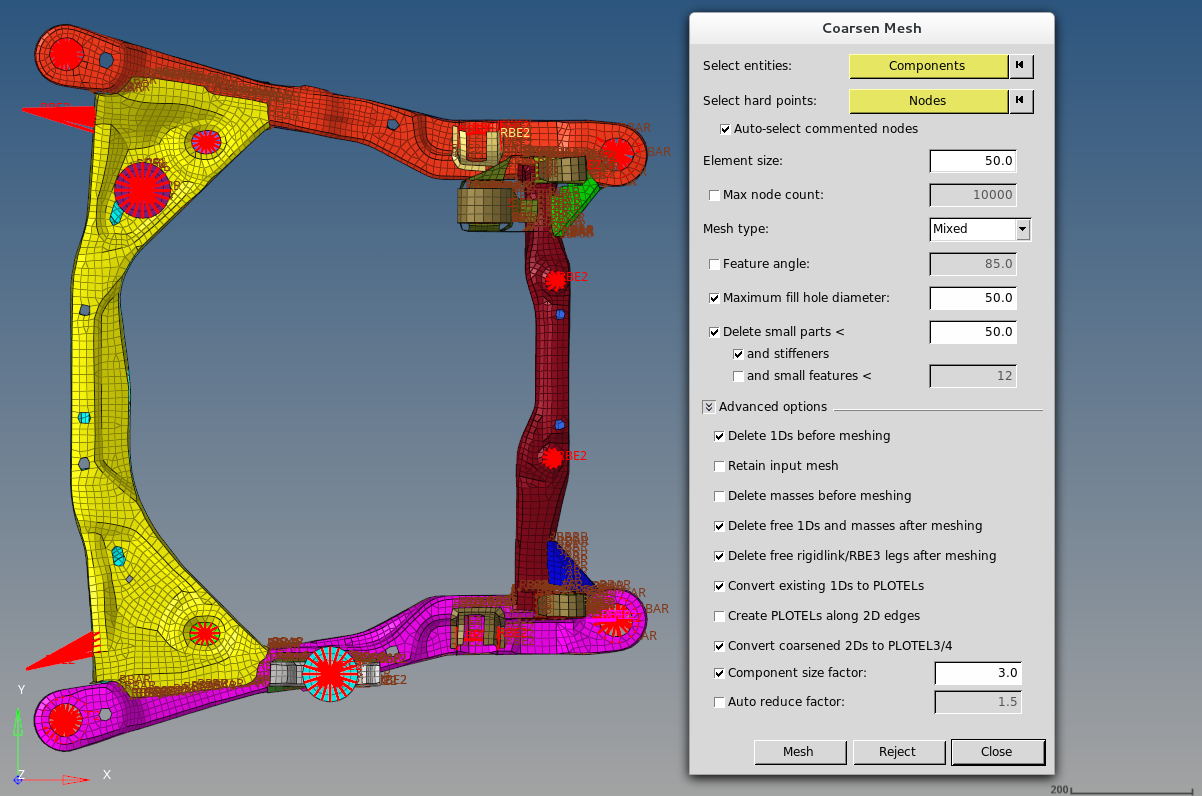
Figure 1. Before Coarsening


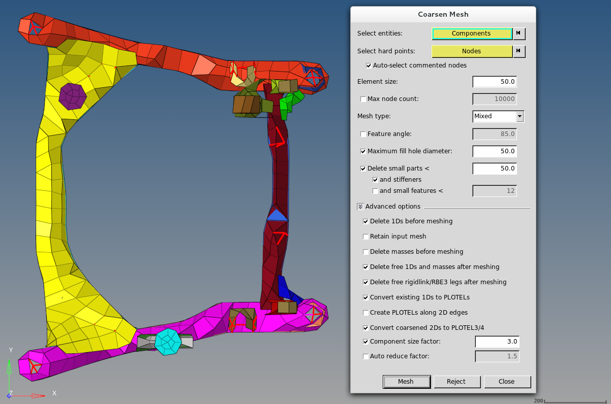
Figure 2. After Coarsening

When a mesh is coarsened like this, it is important to note that every node in the coarse mesh corresponds exactly to one of the nodes in the original mesh, although many nodes are removed, the ones that remain are still the same nodes from the original model. No locations or qualities are changed. Similarly, any nodes or points with special information, such as comments, in the 10th column of their deck will be preserved.

It is best to filter out components that are not relevant to your analysis. In the example above, the wheels and suspension were removed from consideration.

  1. From the menu bar, click Mesh > Create > Coarsen Mesh.
    The Coarsen Mesh dialog opens.
  2. Use the Select entities: Components selector to select the components to simplify.
  3. Use the Select hard points: Nodes selector to select any hard points, such as those defining a hole or ridge, that must be preserved.
  4. In the Element size field, enter a new element size.
  5. To prevent the coarsened mesh from exceeding a target number of nodes, activate the Maximum Node Count checkbox.
    This is an iterative process and will adjust the mesh size you specified accordingly.
    Tip: This option is helpful when you have large models and want to better control the size of the output for NVH models. The maximum node count will apply to all of the selected components. If you would like greater control of a specific component, coarsen that component separately.
  6. For Mesh type, select a mesh type.
  7. To eliminate and mesh over features with angles smaller than the specified value, while preserving features with angles greater than the specified value so that the mesh aligns with the feature line rather than allowing elements to cross over it, activate the Feature angle checkbox.

    The coarsening process uses two stages; if the first stage fails on some elements, the second stage is run. The feature angle setting only applies to the second stage; it is irrelevant to the initial stage.

  8. To mesh over holes smaller than the specified value, but preserve holes that are at least the specified value, activate the Minimum fill hole diameter checkbox.
  9. To remove most features that become detached during the coarsening process, which are underneath the target input size that you specified, activate the Delete small parts checkbox.
    The entire feature must be within this limit. For example, a free bolt hole that is three units in diameter but 25 units in length will remain if this amount is less than 25.
  10. Define advanced options.
    Option Description
    Delete 1Ds before meshing Consider any 1D elements that are part of the input selection for this operation. If those 1D elements are attached to a hard point or are part of a 1D path back to the 2D/3D structure, those elements are not deleted. Any other 1D elements that are part of the input selection are deleted
    Retain input mesh Generate a new component containing the coarsened elements, leaving the original component and its elements untouched. The coarsened elements will share nodes with the original input mesh.
    Delete masses before meshing Consider any 0D elements that are part of the input selection for this operation. If those 0D elements are attached to a hard point or are part of a 1D path back to the 2D/3D structure, then those elements are not deleted. Any other 1D elements that are part of the input selection are deleted.
    Delete free 1Ds and masses after meshing The coarsening operation itself includes making sure the relevant rigidlink/RBE3/mass elements are connected back to the structure accordingly. For this option rigidlink/RBE3/mass elements are considered free only if all legs are free after coarsening/reconnection is complete.
    Delete free rigidlink/RBE3 legs after meshing Delete any free legs after coarsening and reconnection are complete. As mentioned above, a rigidlink/RBE3 element is only free if all legs are free for the purpose of this tool.
    Convert existing 1D to PLOTELs Convert remaining 1D elements that were part of the input selection to PLOTEL, once all of the above rules have been completed. This includes all legs of rigidlink/RBE3 elements. Every leg of these elements needs to be converted to a separate PLOTEL, for example, a 10 leg RBE3 will be 10 PLOTELs.
    Create PLOTELs along 2D edges Create PLOTELs along all 2D element edges and 2D mesh will be deleted.

    If Convert coarsened 2Ds to PLOTEL3/4 is enabled, then PLOTEL3/4 are also created.

    Convert coarsened 2D to PLOTEL 3/4 Convert all Tria and Quad elements to PLOTEL3 or PLOTEL4 element types configurations.
    Restriction: Only available in the OptiStruct user profile.
    Component size factor Component size factor to convert.
    Auto reduce factor Auto reduce factor to convert.
  11. Click Mesh.
    The selected components are meshed.

If the results are not satisfactory, you can Reject the new coarse mesh, change the options, and try again.