Fuse Mesh
Use the Fuse tool to connect close proximity, overlapping and intersecting parts.
Input assemblies can have intersecting/partial intersecting parts, overlapping parts, or close proximity parts.
Open and Close Shell Fusing Options
The following tables list options and actions for the dialog box.
| Open Shell Fusing | |
|---|---|
| Option | Action |
| Proximity Search Threshold | Type the maximum search distance to find proximity elements between
source and target into this field. Fusing will be performed between
them. Note: You are not required to enter a precise distance, but it
is recommended that you do not define too big of a value compared to
the average distance between the source and target in order to avoid
performance issues.
|
| Perform Remesh | Select this checkbox to remesh elements near the connection based on
the user-defined parameters. Triangle element inputs of the first order will be remeshed. Quad element inputs will be remeshed with mixer elements. |
| Feature Angle | Type the feature angle for the remeshed elements to be captured into this field. |
| Connect Source Free Edge Only | Select this checkbox to connect only the free edges within the user-defined proximity threshold. |
| Fusing Direction | Select a direction to which the source will be projected to the
target:
|
| Create Patch at Connection | Select this checkbox to create new patch elements between source and target. If this option is unchecked, source element nodes will be projected and stitched to the target. |
| Remove Redundant Patches from Target | Select this checkbox to remove redundant patches after fusing is performed that are within the user-defined patch maximum width factor. The value of the maximum width factor is calculated by multiplying the factor with the proximity search threshold. |
| Snap to Features | Select this checkbox to fuse source elements to target elements if
the features fall within the user-defined feature snapping tolerance
factor. The value of the snapping tolerance is calculated by multiplying
the factor with the proximity search threshold. This feature includes free edge, non-manifold edges (t-connection / x-connection), and features based on the feature angle defined in preferences. |
| Close Shell Fusing | |
|---|---|
| Option | Action |
| Proximity Search Threshold | Type the maximum search distance to find proximity elements between
source and target into this field. Fusing will be performed between
them. Note: You are not required to enter a precise distance, but it
is recommended that you do not define too big of a value compared to
the average distance between the source and target in order to avoid
performance issues.
|
| Keep Interface | Select this checkbox to keep common shells between source and target
as they are. Uncheck to remove common shells.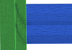 Figure 1. Keep Interface Enabled  Figure 2. Keep Interface Disabled |
| Maximum Search Angle | Type the maximum angle value that is used to detect close proximity between the source and target into this field. |
| Fusing Direction | Select a direction to which the source will be projected to the
target:
|
| Remove Redundant Patches from Target | Select this checkbox to remove redundant patches after fusing is
performed that are within the user-defined patch maximum width factor.
Note: This is only useful in cases of open shells.
|
| Collapse Patches | Select this checkbox to collapse created patches and directly connect
the source nodes to the target nodes. When enabled, you can select a
destination component for patch: Source Component, Current Component, or
New Component. 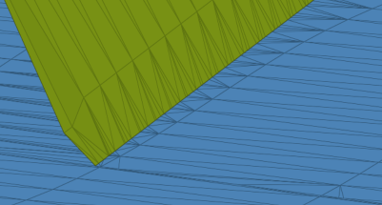 Figure 3. Collapse Patches Enabled 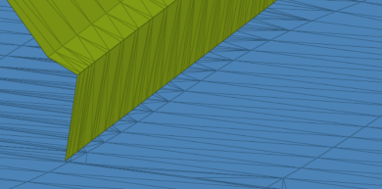 Figure 4. Collapse Patches Disabled |
| Perform Remesh | Select this checkbox to remesh elements near the connection based on
the user-defined parameters. Triangle element inputs of the first order will be remeshed. Quad element inputs will be remeshed with mixer elements. |
| Number of Layers | Type the number of additional layers next to the intersect edge that need to be remeshed into this field. |
| Feature Angle | Type the feature angle for the remeshed elements to be captured into this field. |
| Growth Rate | Type the growth rate for remeshing into this field. |
Fuse Mesh Examples
The Fuse tool can be used with several types of analyses where mesh connections are required.
CFD Fluid Analysis Model Preparation
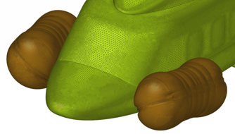
Figure 5.
Thermal Analysis Model Preparation
Figure 6.
Electromagnetic Analysis Model Preparation
Figure 7.