Connector Options Panel
Use the Connector Options panel to set general connector options as well as options specific to spots, bolts, seams, or area connectors.
- Connectors Module
- Accessed by clicking options in the Spot, Bolt, Seam, and Area panels.
General Options Subpanel
| Option | Action |
|---|---|
| fail hexa seam or area connector, if | This criteria is saved for individual connectors, so that
when a realization is performed from the Connector browser
connectors will be considered individually.
|
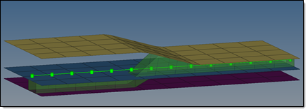
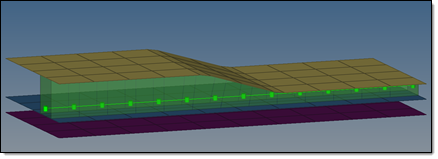
| consider shell thickness and offset for solid positioning | Consider the shell thickness and offset when positioning the
connector. When this checkbox is turned off, the connector is
realized to the ideal shell position.1 This option influences realization types which use hexa elements like ACMs (spot) or hexa adhesives (seam and area) as the realization body. |
| shared entity global options | During connector realization, connecting elements are
created. In order to create a full functional connection,
additional entities and collectors may need to be created. These
entities and collectors are usually shared among several
connectors, therefore they are named shared entities. The shared
entity global options determine how to organize shared entities
and remove shared entities when they are no longer needed.
|
| angle classification for penta (Mig) and hexa (adhesive) | Specify when a penta (mig) and hexa (adhesive) seam connector
becomes a B, L, and T connection.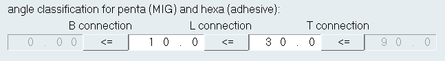 Figure 1. angle classification for penta (Mig) and hexa (adhesive) Example. Angle classifications have been defined for a hexa (adhesive). A B connection will be created when the hexa (adhesive) has an angle between 0° and 10°, a L connection will be created when the angle is between 10° and 30°, and a T connection will be created when the angle is between 30°and 90°. |
Spot Options Subpanel
| Option | Action |
|---|---|
| end offset = / half spacing |
|
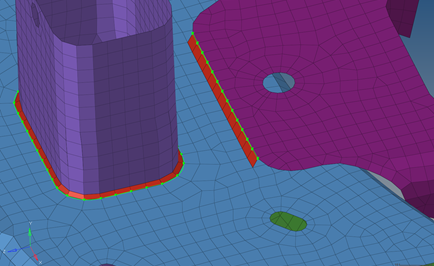
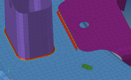
| non-normal projection | Waive the requirement for a normal projection to enable link
candidates to only be found within the connector
tolerance. Typically the link detection requires a valid normal projection to the link candidates (note that an angle of <5° will be considered as normal). If the normal projection is not possible, the realization fails. By default this option is disabled for spots. 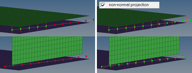 Figure 2. |
| system definition | Allow the creation of coordinate systems along with the
creation of simple 1D FE representations. The y-axis is
collinear with the 1D element the system is located at.
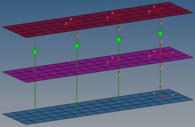 Figure 3. |
| links conservation | Define whether or not extra links should be stored on a spot
or seam connector.
|
| use normal direction of the closest element to determine links | Add links to spot connectors based on the normal direction of
the closest element. This option is useful when there are a
lot of small components, which may result in the wrong
components being determined links.
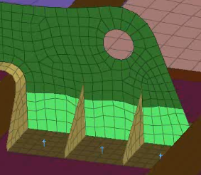 Figure 4. |
| orthogonal faces 1 hexa acm | Create ACM hexa elements as orthogonal as possible. This option overrules the normal shell gap
option.
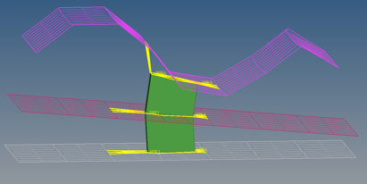
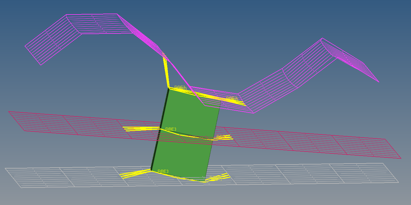 Figure 5.
 If project hexa faces to shell is also enabled, the shell gap will be forced and, at a minimum,
the hexa edges for each hexa pointing from one link to the
next will be parallel to each other.
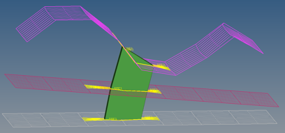 Figure 6. |
| project hexa faces to shell | Investigate and project each individual node, enabling you to
expect and accept penetrations.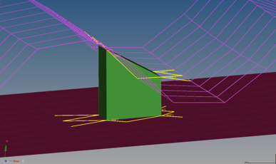 Figure 7. 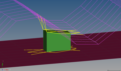 Figure 8. |
| ensure valid projection for shell gap | Mark all hexa node projections to a link that are beyond the
specified tolerance (0.01*diameter) as an error. Tip: Enable this checkbox when working with connections that use
a contact definition.
|
Bolt Options Subpanel
| Option | Action |
|---|---|
| end offset= | If a line is used to create a series of bolts, this will determine how far from the end the connectors will be created. A value of 1.0mm will start the test points 1.0mm in from the line. |
| no systems | Will create a coordinate system according to the selection. No System: Won't create a system. Single System: Will create a system for the whole bolt. 1 system per layer: Will create one system per layer, and so forth. |
| consider bolt collinearity | Will attempt to keep the bolt body straight if the bold has more than 2 layers. |
| auto create missing attachments | Will automatically create missing bolt attachments. |
| minimum needed links | Reduce link candidates to the links which are needed to
perform a valid projection with respect to the specified number
of layers during link detection. For example, for a 3-layer spot connector typically three links are established, even though more than three link entities were selected before and are within the given tolerance. For seam connectors this investigation has to be done per each test point, so that typically the number of links is higher than the number of layers. |
| re-apply during realizations | Remove unnecessary, defined links during realization. Only take into account the links which already exist in the connector. |
| extra links= | Store more link candidates than necessary on a connector.
In addition to the number of layers, extra links can be stored per test point. This means with 5 extra links, a 3-layer spot connector can store up to 8 link candidates or a seam (2-layer) with 6 test points can store up to 42 link candidates. |
Seam Options Subpanel
| Option | Action |
|---|---|
| discontinuity weld length tol | Defines an upper and lower allowed deviation from the
requested discontinuity weld length in %.
|
| links conservation | Choose whether or not to store extra links on a spot or seam
connector.
|
| re-apply during realizations | Remove unnecessary, defined links during realization. Only
the links which already exist on the connector are taken into
account. Note: Only available when link conservation is set
to minimum needed links.
|
| link option | Select how connectors are linked. Seam connectors are
supposed to connect two links at each test point.
|
| sliver elements at free edges | Select how to manage sliver elements in your model that have
an element length less than the value specified in the element
length field, and that are located at free edges. Sliver elements are small elements that you may not want in your model. In the images below, a perfect perpendicular
projection resulted in sliver elements. The red elements
represent the HAZ elements.
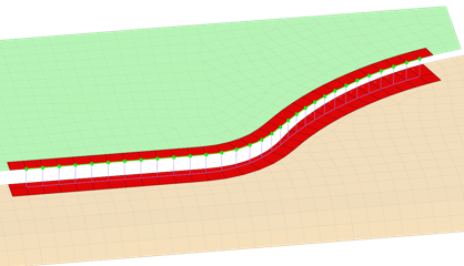 Figure 11. Allow 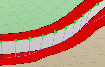 Figure 12. Prevent by Moving Projection Points 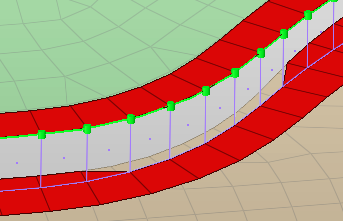 Figure 13. Prevent by Moving Edge 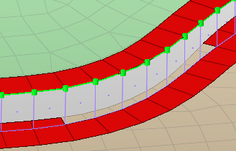 Figure 14. Delete Sliver Elements |
| element length < | Sliver elements in your model that have an element length less than this value will be managed by the sliver elements at free edges option. |
| washer preservation | Select how to modify washer elements close to seams.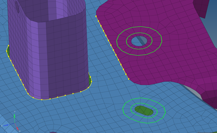 Figure 15. Washer Elements Example. Washer elements are colored green.
|
| don't share zone elements | Prevent the sharing of zone elements. To generate seam
welds with the desired size of imprinted elements, even if
the seam welds are close to each other, imprinted elements
can be shared among two connectors.
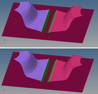 Figure 19. |
| max quadsize reduction in % | Specify the maximum deviation from the requested imprint quad
element size. By default, this value is set to 30.0%. It can
be set from 5.0% to 80.0%.
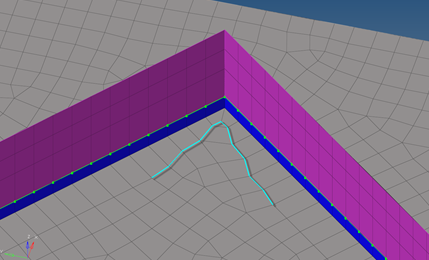 Figure 20. |
| max quadskew in degrees | Specify the maximum deviation from an ideal right angled
quad. By default, this value is set to 30.0°. It can be set
from 5.0° to 45.0°.
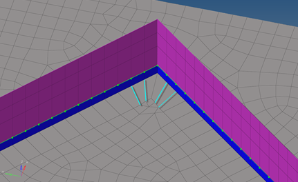 Figure 21. |
| feature angle | If the nodes of the mesh are not associated with surfaces, the feature angle is needed to identify the features, which might need to be protected. By default, this value is set to 30.0°. The minimum value is 10.0°. Features will not be protected when they are close to imprint regions. |
| corner quads | If seams are not smooth and contain vertices, a different
mesh pattern in those corner may be requested.
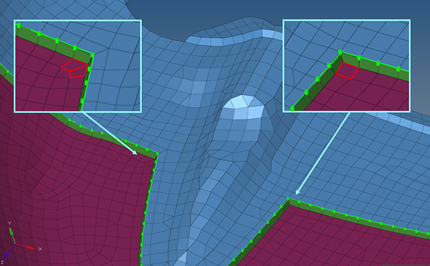 Figure 22. |

Area Options Subpanel
| Option | Action |
|---|---|
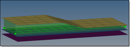
| non-normal projection | Abrogate the requirement for a normal projection, so the link
candidates only need to be found within the connector
tolerance. By default this option is deactivated for
areas. Typically the link detection requires a valid normal
projection to the link candidates.
Note: An angle of 5
degrees or less will be considered as normal. If the
normal projection is not possible, the realization
fails.
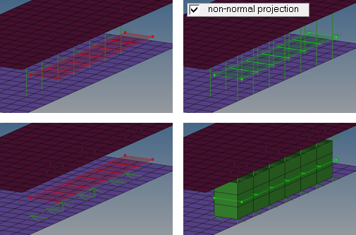 Figure 23. |
| link option | Select how connectors are linked. Area connectors are
supposed to connect two links at each test point.
|
Apply Mass Options Subpanel
| Option | Action |
|---|---|
| check for missing link | Before re-realizing an unrealized connector, check the links
in the connector. If any of the links do not exist, the
connector will fail. Clear this checkbox to rerealize any unrealized connector if at least 1 of the links still exists in the connector. |
Fe Config Subpanel
Use the fe config panel to load a custom feconfig.cfg file, or unload a feconfig.cfg file that was previously loaded.
If you load a feconfig.cfg file that contains config types with IDs or names that already exist in the current HyperMesh database config list, the duplicated config types will be skipped during the loading process. To overwrite the existing config types with the new config types, select overwrite if a config ID or name exists.
-
- T Connections
-
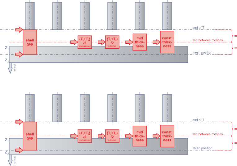
Figure 26. Consider Shell Thickness and Offset for Solid Positioning Disabled. Hexas are positioned around the midplane between the mesh.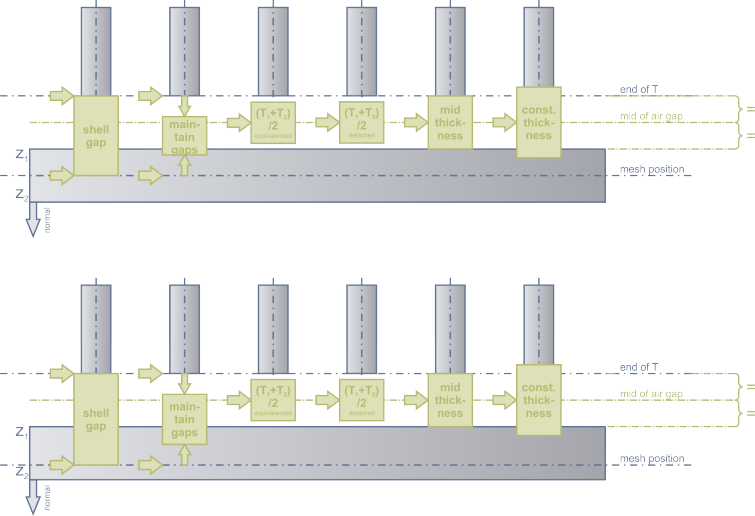
Figure 27. Consider Shell Thickness and Offset for Solid Positioning Enabled. Hexas are exactly positioned around the mid air gap. - Lap Connections
-
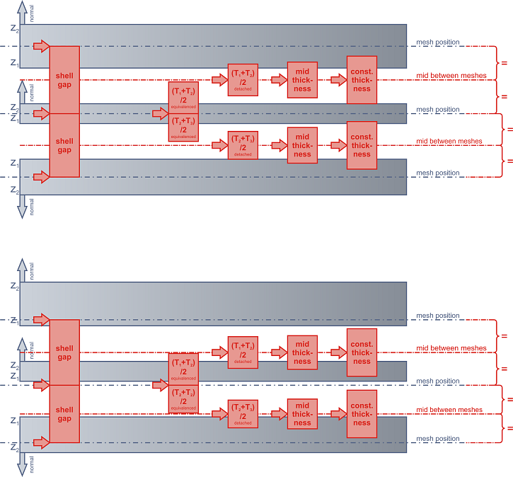
Figure 28. Consider Shell Thickness and Offset for Solid Positioning Disabled. Hexas are positioned around the midplane between the mesh.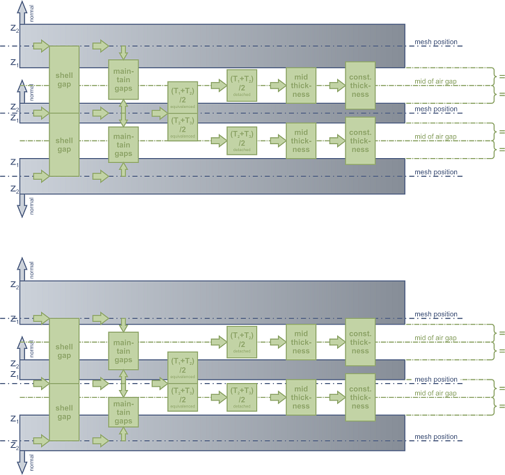
Figure 29. Consider Shell Thickness and Offset for Solid Positioning Enabled. Hexas are exactly positioned around the mid air gap.