Morph Panel
Use the Morph panel to morph the model and create shape entities.
Location: Tools page > HyperMorph module
Settings made on one subpanel are not lost if you switch subpanels, but may be lost if you return out of the panel.
Common buttons found in many of the Morph subpanels include undo, redo, undo all, and redo all. Use these buttons to move forward or backward through the morphs that you have applied to your model. They remain active when you leave the panel but are not saved with your model unless you select the save morphs with file checkbox in the global subpanel of the Morph Options panel. Thus you could either perform an undo all before saving your model in order to return it to the unmorphed state, or select the save morphs with file checkbox to save all of the morphs on the undo/redo list along with the file so that they can be undone when the file is reloaded. You can also clear or compress the morphs stored in the undo/redo list in the global subpanel of the Morph Options panel.
Many subpanels of the Morph panel contain a button labeled options. This button replaces the symmetry links and constraints checkboxes from earlier versions of HyperMorph. Clicking this button will take you to the Morph Options panel where you are able to adjust a large number of parameters that affect morphing.
Move Handles Subpanel
Use the Move Handles subpanel to move handles and morph a mesh.
In the morph options panel, morphing subpanel, there is an option for setting the minimum step size for interactive morphing. If the distance or angle fields are set to values other than zero the morphing will be performed in discrete steps with the given step size rather than an arbitrary value based on the position of the mouse and relative to the size of the model. For example, setting the distance to 1.0 means that all interactive translation will be performed in increments of 1.0, such as 1.0, 2.0, 11.0, and so on. For distance, the value is given in model units. For angle, the value is given in degrees.
If the morphing is too slow, change from real time to on release (morphing will occur when you release the mouse button).
If you select more than one handle before selecting morph, those handles will follow the handle that you are dragging.
If you have enabled fea results, an FEA solution will be performed in real time or on release depending on the selected setting in the morph options panel.
| Option | Action |
|---|---|
| movement type | Choose type of
movement for the selected handles.
|
| on/along what | Choose where the
movement is allowed to take place, including in what
directions.
|
| along mvol edges | When morphing along mvol edges, use this selector to pick the desired edges. |
| along vector: plane and vector selector | Define or select the
vector along which to morph. Note: Available for translate,
project to line, project to surf, and project to mesh
morphs.
|
| angle = | When rotating handles, specify the number of degrees to rotate by. |
| avg for origin / origin = | When morphing by scale, choose between using the average of the selected handles' coordinates for the origin or select a specific node as the origin. If using the avg for origin option you must select more than one handle to morph. |
| constant/linear |
Note: Available when rotating handles.
|
| handles | Select the handles you wish to move. Moving handles morphs the mesh of their dependent nodes. |
| line | When morphing along line, use this selector to select the desired line. |
| node | When morphing by move to node, use this selector to select the node that you wish to move the selected handle(s) to. |
| normal to geom | Set the projection
direction normal to the target geometry (line list, surfs, or
elems). Note: Available for project to line, project to surf,
and project to mesh morphs.
|
| normal to elems: all 2D elems / elems | Set the projection
direction normal to elements touching the handles, or normal to
specific elements that you select via the elems
selector. Note: Available for project to line, project to
surf, and project to mesh morphs.
|
| on plane: plane and vector selector / infer from handles | Choose how to define
the plane.
|
| options | Open the Morph Options panel. |
| point | When morphing by move to point, use this selector to select the geometric point that you wish to move the selected handle(s) to. |
| project to plane | When projecting to a
plane, choose a method for determining the position and
orientation of the plane. Each option also requires a base node
(B node collector).
|
| project to plane | When projecting to a
plane, choose a method for determining the direction to project.
|
| real time / on release |
Note: Only available for interactive morphing.
|
| rotation axis | When rotating handles, use the plane and vector selector to define a vector. This vector (at the base node) is the axis of rotation, and its positive direction is determined via the right-hand rule. |
| surf | When morphing on surface, use this selector to select the desired surface. |
| system = | Specify a local
coordinate system for the translation or scaling dimensions,
otherwise the default global system is used. Note: Available when
on/along what is set to along xyz or scale.
|
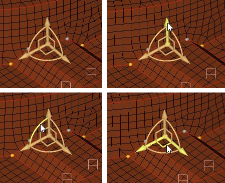
| true rotation | Clear this checkbox to
rotate the handles, with the mesh morphed linearly according to
their new locations (left image, following). When selected, true
rotation rotates both the nodes and the handles, with the amount
of rotation for the nodes being proportional to the amount of
influence of the handles over those nodes. (right image,
following).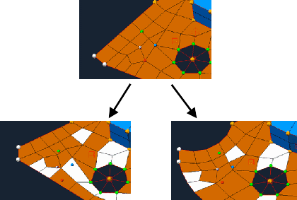 Figure 6. |
| x scale, y scale, z scale | Specify the
magnitude/distance in each axis for the scaling, in model
units. Note: Available when on/along what is sets to
scale.
|
| x value, y value, z value | Specify the distance
in each axis for the translation, in model units Note: Available
when on/along what is sets to move to xyz.
|
| uniform | When morphing by scale, set all of the X, Y, and Z values to the same number. A pop-up allows you to specify the desired number, and displays the average of the three existing values by default. |
| use all elems / elems | When morphing along normal, choose the direction as the average of all involved elements' normals, or to select specific elems. |
| use system for nodes | Move influenced nodes
relative to the local system instead of following the
handles. Note: Available when on/along what is set to
translate or scale.
|
Alter Dimensions Subpanel
Use the Alter Dimensions subpanel to morph your mesh by selecting a dimension in the model and changing its values.
There are five dimensional types that can be altered: distance, angle, radius, curvature, and arc angle.
For distance and angle, you define the dimensions by selecting domains, nodes and/or handles that will be used to alter the dimension.
If you have any reflective symmetries (1-plane, 2-plane, 3-plane, and cyclical) in the model, the changes applied to any domains assigned to those symmetries will automatically be reflected to all linked domains.
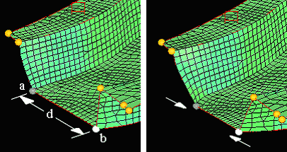
Figure 7.
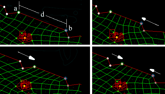
Figure 8.
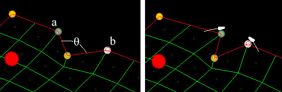
Figure 9.
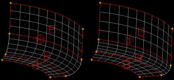
Figure 10.
Figure 11.
Figure 12.
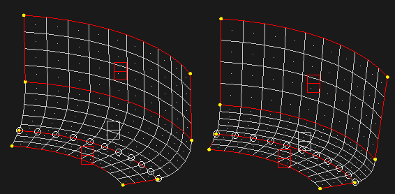
Figure 13.
| Option | Action |
|---|---|
| dimensional type | Choose the type of
dimension that you wish to alter.
|
| entities to use | Choose the type of
entities to use.
|
| add to current | When morphing by radius or arc angle, add the value of radius = or arc angle = to the existing radius or arc instead of replacing it. |
| along: a to b / N1 N2 / x-axis / y-axis / z-axis | Choose the direction
of the movement.
|
| center calculation | Choose a method of
center calculation.
Note: Available when morphing by radius, curve ratio, or
arc angle.
|
| edge domain: domain | Morph by distance along an edge domain. |
| edge and 2D: domains | Select one or more
edge and 2D domains. For every 2D domain you must select at
least one edge domain which touches it. The average radius of
the selected domains automatically appears in the radius =
input. Note: Available when morphing by radius, curve ratio,
or arc angle.
|
| end a: | Specify one end of the
relevant distance. Depending on the setting of the entities to
use switch, this will require you to select a handle, node, or
node a. Note: Available when morphing by distance or
angle.
|
| end b: | Specify one end of the
relevant distance or angle. Depending on the setting of the
entities to use switch, this will require you to select a handle
or node b. Note: Available when morphing by distance and two
handles or nodes and handles, or by angle and nodes and
handles.
|
| followers (end a): handles | The selected follower
handles will move as end a moves. Note: Available when morphing
by distance with nodes and handles.
|
| followers (end b): handles | The selected follower
handles will move as end b moves. Note: Available when morphing
by distance with nodes and handles.
|
| force edges circular | Force the selected
edge domains to be circular after morphing. Note: Available when
morphing by radius, curve ratio, or arc
angle.
|
| force edges flat | Project the nodes of
selected edge domains to a plane prior to
morphing. Note: Available when morphing by radius, curve
ratio, or arc angle.
|
| hold center / fillet / hold ends / hold end | Choose how the center
of the radius is treated with respect to movement during the
morph.
Note: Available when morphing by radius, curve ratio, or
arc angle.
|
| hold end a / hold end b / hold middle | Choose which portion of the line between the selected ends remains fixed, and therefore determines which of the two ends moves. |
| interactive | Perform the morph in
real-time by clicking and dragging handles with the mouse. When
inactive, morphing only occurs when you click
morph.
|
| normal to: abv plane / N1 N2 / x-axis / y-axis / z-axis | Choose the orientation
of the angle normal to an existing entity or direction.
Note: Available when morphing by angle.
|
| options | Open the morph options panel. |
| preview only | Preview the morph
without actually changing the mesh. Note: Available when morphing
by radius, curve ratio, or arc angle.
|
Set Biasing Subpanel
Use the Set Biasing subpanel to change the biasing factors associated with each handle. You must click update to apply bias changes to the handles, unless you update them interactively.
Clicking screen edit will display edit windows for the bias factors if they are not displayed or hide the edit windows for the bias factors if they are displayed.
The initial bias factor for all handles is 1 except for dependent handles automatically generated at the ends of 1D domains which are given a bias factor of 3. Higher bias values will increase the influence that handle has over nearby nodes. Lower bias values decrease the influence. Bias values of 1 give linear results that result in morphs with sharp angles at the handle locations.
For exponential biasing a bias value of 2 will result in morphs with a gentle curvature through the handle locations. Using bias factors of 1 at the corners of a model and 2 everywhere else will generally give a smoothly morphed model.
For sinusoidal biasing a bias value of 2.0 for a handle at one end of an edge domain and 0.5 for a handle at the other end will give a perfect circular or elliptical curve for the domain. For values of 3.0 and higher the influences will obey a sine-cosine curve with a frequency equal to one-half cycle plus one for each full step above 3.0 (that is 4.0 gives a frequency of one and one half cycles, 5.0 gives two and a half, and so on). Values between 2.0 and 3.0, or 3.0 and 4.0, or 4.0 and 5.0, and so on, blend the influences of a full sine-cosine curve at the higher value with that of a linear curve. In other words, a bias factor of 4.7 will give influences that are 70% of what they would be for a biasing factor of 5.0 and 30% of what they would be if they were linear.
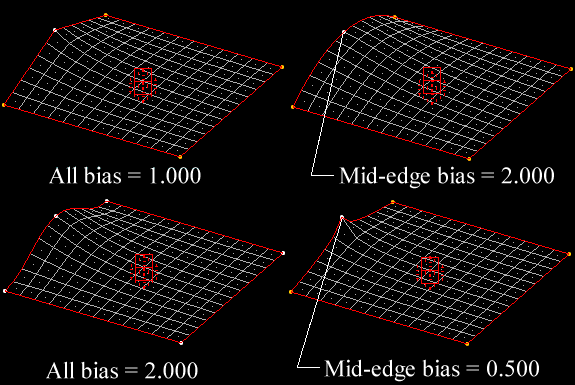
Figure 14.
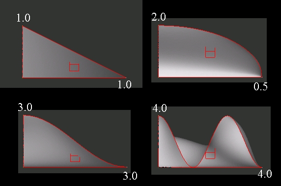
Figure 15.
| Option | Action |
|---|---|
| bias = |
|
| biasing style: exponential / sinusoidal | Set the biasing style to apply. |
| handles | Select the handles for which you wish to apply biasing. |
| make retroactive | Adjust the morphs currently applied to the model to reflect the new biasing factors. |
| options | Open the morph options panel. |
Set Constraints Subpanel
| Option | Action |
|---|---|
| (constraint type switch) | Choose the type of
constraint to apply.
|
| color | Select a color in which to draw the constraint. |
| name = | Specify a name for the constraint entity. |
| nodes | Select the nodes to be constrained. |
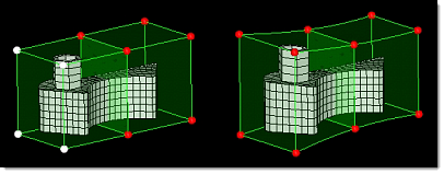
| stretch mesh around nodes |
Stretched the mesh near the constrained nodes proportionally
to their distance from the nodes, in order to create a smoother resulting mesh.
Clear this checkbox to not stretch the mesh.
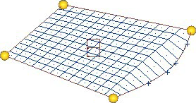 Figure 16. No Mesh Stretching 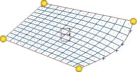 Figure 17. Mesh Stretching Enabled |
Save Shapes Subpanel
| Option | Action |
|---|---|
| as handle perturbations / as node perturbations | Shapes saved as handle perturbations take up less space and can change if the domains and handles for the model are changed. If you edit the domains and handles in a model that has saved shapes or morphs on the undo/redo list, you will be given the option to preserve those shapes as node perturbations. If you click yes, the shapes will retain their original form. If you click no, the shapes will be unchanged internally, but may be appear different due to changes in the influences of the perturbed handles. |
| color | Select a color for the current shape. |
| global system / syst | Shapes must reference a coordinate system which affects both how the shape is applied and how it is written to a data file. When a shape is applied to the model the shape's perturbations are converted into the system's coordinates, scaled, and then converted back into the global system. This allows a shape which references a cylindrical or spherical coordinate system to rotate through an angle when scaled rather than move linearly when applied. Also, when a shape which references a local coordinate system is written to a data file the perturbations will be converted into local coordinates and the shape will reference the local coordinate system. |
| name = | Specify a name for a new shape, or click the button twice to select an existing shape. |
Apply Shapes Subpanel
| Option | Action |
|---|---|
| multiplier = | When applying the shapes by factor, the value in the multiplier = field determines the intensity of the shape-based morph. This is a simple multiplier, so 1.0 is the same size as the input shape, while 2.0 is twice as large, and so on. |
| shapes | Use this entity selector to select the desired shapes. |
Morph Surfaces Subpanel
Use the Morph Surfaces subpanel to morph the surfaces in the model to adhere to any morphing of mesh nodes that were previously associated with them.
There are no inputs on this subpanel; all surfaces are morphed when you click morph surfaces. If the results are unsatisfactory, you may reject them.
Command Buttons
| Button | Action |
|---|---|
| animate | Automatically generate and load a "results" file based on the selected shapes, which you can then view with any HyperMesh post processing feature. |
| apply | Apply the selected shapes when on the apply shapes subpanel. |
| constrain | Set the chosen type of constraint on the selected nodes. |
| morph | Perform the morphing operation based on all available input. |
| morph surfs | Morph the surfaces in the model to adhere to any morphing of mesh nodes that were previously associated with them. |
| redo | Redo the last "undone" operation. |
| redo all | Redo all "undone" operations. |
| reject | Undo the creation of an entity, such as a constraint or shape. |
| return | Exit the panel. |
| save | Save the shape. |
| undo | Undo the most recent morphing action (movement of nodes, but not creation of entities such as constraints). |
| undo all | Undo all recent morphing actions (movement of nodes, but not creation of entities such as constraints). |
| update | Update the biasing factor or method for the selected domains. |