Altair HyperXtrude 2021.2 Release Notes
Altair HyperXtrude is a suite of finite element solvers for simulating the following
manufacturing processes.
- Metal Extrusion
- Polymer Extrusion
- Quenching
- Calibration
- Metal Rolling
- Friction Stir Welding
- Resin Transfer Molding
Highlights
A new solver for binder jet sintering with interfaces in HyperMesh and Inspire has been added. This solver comes with a comprehensive set of features to meet the needs of the industry.
All Solvers
New Features
- Updates to H3D Writer Module
- H3D files exported from the solver now use version 2021.0 of the H3D writer libraries. This change enabled the interfaces to create on-demand results in SI units from the exported results in user units. However, this did not support plotting the results on boundary faces. In this version, an additional FEM file containing the BC data is also exported from the solver to enable plotting the results on BCs. With these two changes, the solver will no longer have to write two H3D files to support post-processing in Inspire and HyperView. It will export only results in user-specified units. Interfaces will automatically generate the results in SI units on-demand at the time of post-processing.
Binder Jet Sintering
Binder jet printing is a 3D additive manufacturing technique and it is becoming
increasingly popular. It is used to make complex metal parts with excellent
mechanical properties. It costs significantly less than other AM methods. This
process is followed by a heat treatment process in an oven known as sintering. This
is a long process and typically happens for 10+ hours. During this process, the
metal particles in the part come together leading to part densification and
significant part shrinkage. This heat treatment process has three stages: Debinding,
Sintering, and Cooling. The part before the debinding stage is called the green
part, and after the debinding stage is called the brown part. The process of
debinding removes the binding agent and it can be done chemically. The main design
questions are centered around the sintering part of the heat treatment process.
During this stage, the metal particles come together and the part densification
occurs. The key questions a designer of this process may have are:
- For a given brown part and the oven temperature curve, how much does the part shrink?
- What should be the size of the green part to achieve the final part shape and tolerances?
- How to evaluate the efficiency and improve the oven temperature curve?
The solver supports two types of analysis:
- Shrinkage prediction analysis
- Geometry-based shrinkage compensation analysis
Enhancements
- Shrinkage Prediction Analysis
- The goal of this analysis is to predict the part shrinkage for the given green part and the oven temperature curve.
- Supported Results:
- Displacement
- Velocity
- Temperature
- Relative Density
- Sinter Deviation
- Volume Change
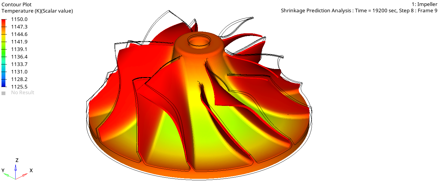
Figure 1. - Geometry Based Shrinkage Compensation Analysis
- The goal of this analysis is to determine the brown part geometry from the desired final part shape and tolerances. This is an efficient design optimization analysis and is completely performed by the solver without any external optimization tool.
Metal Extrusion
Enhancements
- User-Defined Functions for Material Model - Element ID
- The solver sends all relevant data to the interface to compute the flow stress and this previously did not include the element ID. In this version, based on a customer request, the correct element ID is also included in this list.
- User Control in Partitioning Dead Cycle Time
- The solver has added a new parameter DeadCycleTimeInContainer to control how much of the dead cycle time (DeadCycleTime) is inside the Container. The rest of the time, it will be outside the Container. If this parameter is not specified, the solver will use the current default of 50% of the time outside the Container and the remaining 50% of the time inside the Container.
Resolved Issues
- Symmetric model gives Asymmetric OptiStruct results
- The HyperXtrude solver writes the loads on the workpiece - tool interfaces to perform the stress analysis using OptiStruct. These loads are computed by performing the extrusion analysis until the specified convergence. The loss of symmetry could happen for a few different reasons, such as asymmetric mesh and numerical oscillations. In this particular case, the projection and mapping algorithm was improved to address this issue in the reported model.
- Incorrect Heating During Dead Cycle Time
- The dead cycle time is divided into two parts. In the first part, the hot billet is outside the container. Therefore, it should lose heat, and the container also should lose heat. The solver was showing the container gaining heat due to incorrect convection reference temperature. This issue is resolved by correctly setting the reference temperature.
Polymer Extrusion
Resolved Issues
- Random Memory Errors
- An underlying cause for a random memory error was identified and resolved.
Friction Stir Welding
Enhancements
- Pin Deflection Analysis - Post Processing in Inspire FSW
- The exported FEM file is now organized into components using HM comments to enable post-processing of the pin deflection analysis results in Inspire FSW. In this release, Inspire will automatically launch the OptiStruct run and enable post-processing.
Quenching
Enhancements
- Initial Conditions using Extrusion Results
- The solver is enhanced to automatically map extrusion flow analysis data, temperature and grain size as the initial conditions for the quenching analysis. This feature is also available for use in Inspire Extrude.