Altair Multi Body Solutions 2021.2 Release Notes
Highlights
- New MotionView Interface (Beta)
- MotionSolve-Activate-EDEM Co-Simulation
- Bearing Elements
- CM Labs-Vortex Translator
- Multi-Disciplinary Tools Enhancements
- 1D Electronic Stability Program (ESP)
- Vehicle Aerodynamic Forces
- Altair Driver Updates
- N-Post Shaker Updates
- Tire Test Rig
- Vehicle Example Models
- 1D Traction Control Update
- CD Tire Licensing Update
- Other Enhancements
- Resolved Issues
New MotionView Interface MVX (Beta)
Over the next several releases, MotionView will be transitioning to a new graphical user interface framework and interface. A beta version of the first release of the new interface (MVX) is now available (HyperWorks 2021.2 MV in the Start menu).

Figure 1.
- Move Tool for model repositioning.
- Rigid Groups - Group rigid bodies that move together.
- New interactive contexts for Points, Joints, and Markers.
- Show/Hide/Isolate features.
- Ability to change variable names.
- Live animation during Static and Transient solutions with MotionSolve (experimental – use environment variable HW_MV_LIVE_ANIMATION = 1).
MVX supports all existing functionalities that are available in the current interface. Both versions, MVX and MotionView (MotionView 2021.2 from the start menu) co-exist and can be used interchangeably today. However, the new capabilities highlighted above are only available in MVX.
MVX is being released as a beta functionality to solicit early usage and feedback for improvement. The functionality may contain unidentified defects.
Activate, MotionSolve, and EDEM Co-Simulation
MotionSolve can interface with Altair EDEM, a state-of-the-art bulk material simulation tool. EDEM is based on the Discrete Element Method (DEM) that simulates and analyzes the behavior of bulk materials, such as sand, granules, capsules, grass, rock masses, and so on. In this co-simulation the mechanical part is modeled in MotionSolve and the bulk material is defined in EDEM. MotionSolve is the leading solver.
MotionSolve can also interface with Altair Activate, a solution for creating and simulating multi-disciplinary, dynamic system models. Activate is especially useful for signal-processing and controller design that requires both continuous-time and discrete-time components. In this co-simulation, the mechanical part is again modeled in MotionSolve, but the controller or other signal-processing designs are modeled in Activate. MotionSolve models are added as system block into the Activate model. In this case, Activate is the leading solver.
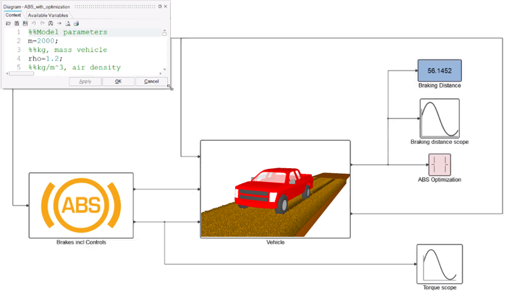
Figure 2.
Bearing Elements
Bearings are involved in almost all mechanisms, such as gearboxes, engines, robotic arms, and so on. In traditional Multibody Dynamics, bearings are often simplified by kinematic constraints, such as revolute of cylindrical joints, or by bushings. To overcome this impediment, MotionSolve was expanded with bearing components designed particularly for system analysis, that is, they were designed to accurately replicate the non-linear compliance of bearings but are simplified enough to accommodate the need for high computational performance. The bearing components require only simple user inputs that can be found in many bearing catalogs. Their results can be used to study bearing loads and their life expectancy. The bearing components are developed on top of the MotionSolve API. They do not exist in MotionView yet. Their support in MotionView will be released in the future.
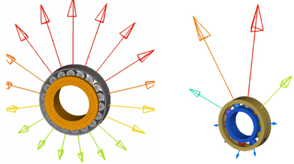
Figure 3.
Activate Contact Iteration (Beta)
MotionSolve allows you to define a 2-D or 3-D contact force between two rigid bodies. Each body is characterized by a set of one or more geometries which can be a 3D mesh, an analytically defined solid, or a 2D curve. Whenever any geometry on the first body penetrates any geometry on the second body, contact normal and frictional forces are generated. In this release, the rigid-to-rigid contact algorithm has been expanded with an “Active Contact Iteration” option that allows penetration to be updated during iteration using the analytical Jacobian. This feature reduces noise in the contact forces.
<Param_Simulation

contact_iteration = {"ACTIVE | INACTIVE”}

/>
This feature is being released as a beta functionality to solicit early usage and feedback for improvement. The functionality may contain unidentified defects.
Translator to Vortex-Studio
Vortex-Studio is a real-time simulation and visualization software by CM-Labs, an APA partner. A MotionView to Vortex-Studio translator is now available. Using the translator, a MotionView model can be translated to Vortex-Studio to simulate and visualize a proven multi-body system in real time for human-in-loop testing and immersive training. (https://www.altair.com/resource/introduction-to-vortex%C2%AE-studio-by-cm-labs-simulations)
| Entities | Comments |
|---|---|
| Bodies | Rigid body only. Flex body and NLFE body is not supported. |
| Graphics | CurveGraphics, Outline, Spring, Tire graphics are not supported. |
| Joints | CV Joint, Screw Joint are not supported. |
| Motion | Linear only. Curves, Spline3D, and Expressions not supported. |
| SpringDampers | Linear only. Curves, Spline3D, and Expressions not supported. |
| Bushings | Linear only. Curves, Spline3D, and Expressions not supported. |
| Forces | Linear only. Curves, Spline3D, and Expressions not supported. |
| Contacts | Only a collision rule is defined in vortex. No other contact properties are translated. |
To use the translator, load the preference file (File > Load > Preference File) CM Labs Vortex Studio Tools that will add a Vortex menu. The menu contains a Settings dialog that will help to associate Joystick actions to motions in the model and cameras on bodies.
Multi-Disciplinary Tools Enhancements
- New paired versions of actuation features are introduced; namely twinrod, twinstrut, and twinactuator.
- New attachment feature "rod2cylinder" is introduced to define a rod to cylinder connection made of two equivalent cylindrical joints with friction based on deformable curves.
- Improvements in existing rod, strut, and actuator features to align their behavior with the new paired versions of actuation.
- Improvements in cable feature and all related cable demo models.
- A bug related to units' management has been fixed in "road4durability" feature of Automotive.
- Loading of Compose feature (Plot FRF) for MotionSolve in Activate has been automated.
- Improved solids2motion and meshes2motion features to support meta characters in component names.
1D Electronic Stability Program (ESP)
MotionView adds a new 1D Electronic Stability Program (ESP) controller for the Car/Small truck library. The ESP is a driver assist system that improves the vehicle’s stability through intervention in the braking system. By individual wheel braking ESP can control the yaw moment of the vehicle, thus its steering behavior.
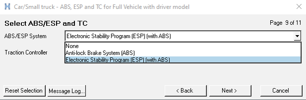
Figure 4.
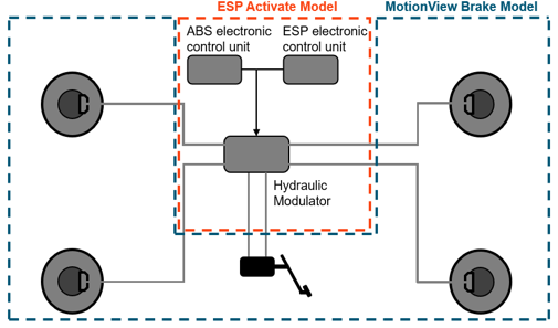
Figure 5.
Aerodynamic Forces in Vehicle Models
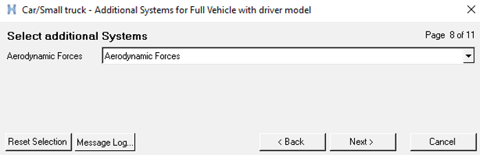
Figure 6.
The aerodynamic parameters are entered in a TeimOrbit property file .aae including Environment parameter; Wind velocity; Side Forces; Drag, Lift, Yaw and Roll coefficients.
Altair Driver Updates
The vehicle models in MotionView uses by default the -X as forward direction and -Y as left direction. In previous release the Altair Driver only accepted the default vehicle modeling coordinate system to simulate the events.
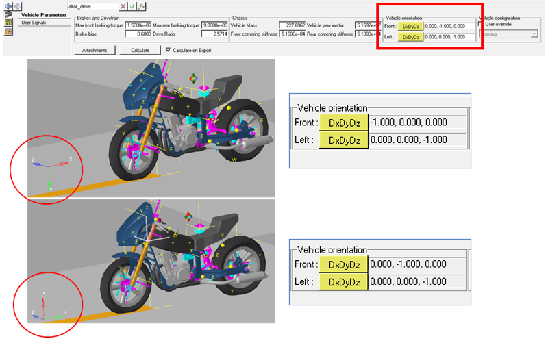
Figure 7.
N-Post Shaker
The N-post Shaker can now be used to simulate event with vehicles in any coordinate system. In previous release, as for the Altair Driver, the vehicle could only have -X as forward direction and -Y as left direction.
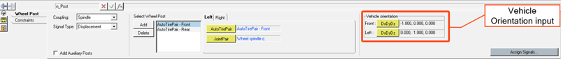
Figure 8.
Tire Test Rig
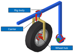
Figure 9.
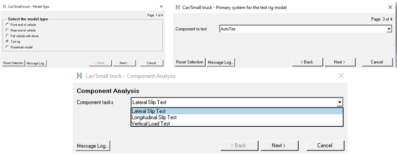
Figure 10.
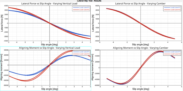
Figure 11.
New Vehicle Example Models
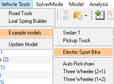
Figure 12.
- Electric Sport Bike: A motorcycle model parametrized to enable AltairDriver
at any coordinate system, including an electrical powertrain.
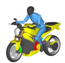
Figure 13. - Pickup Truck: A 4x4 vehicle with an IC engine and ABS control model.
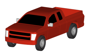
Figure 14.
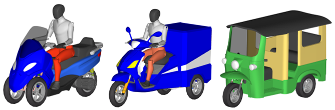
Figure 15.
1D Traction Control Update
In the 1D Traction Control, FWD and RWD had to be specified in the 1D Activate model before exporting the FMU. In this release a switch was added in the Traction Control system in MotionView. By selecting FWD or RWD vehicle Traction, the controller is defined automatically to the desired setting. If the drive axles is switched after creating the model, then the proper value for traction control needs to be set inside the traction control Forms.
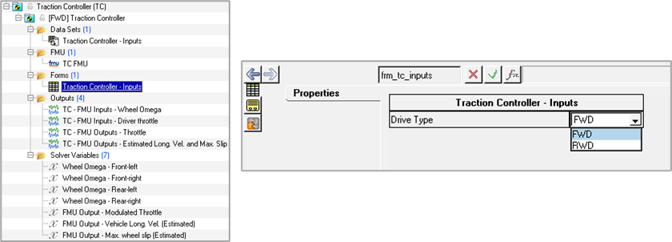
Figure 16.
- Known Issue
- Traction Controller does not work for 4WD/AWD configuration vehicles. The option to add Traction Controller for such vehicles has been withdrawn.
CD Tire Licensing Update
CD-tire files can be used with Altair MotionSolve either by enabling the CD-Tire licensing with Altair licensing or using the CD-Tire standalone license.
- ALTAIR_LICENSE_FOR_CDTIRE=1
- Altair license file will be checked for CDTire license. If it fails, Flexlm licensing will be checked for CDTire’s own license.
- ALTAIR_LICENSE_FOR_CDTIRE≠1 or not available
- Flexlm licensing will be checked. If it fails, MotionSolve will exit the simulation.
Other Enhancements
- CAD graphics reading performance has been significantly improved.
- The new SpringDamper graphic has options to control the display of the spring and the damper.
- Graphics has a new attribute “hide_in_post” to avoid writing the graphics into MotionSolve result h3d after the simulation.
- Validity checks are now performed for properties of Beams and Polybeams.
- Datasets attributes are now available for edit in Data Summary.
- FlexTire file created during transfer of AutoTire to EDEM has been updated as per latest form prescribed by Pratt-Miller/FlexTire.
- The “Auto color” option in View Reports has been changed to “Use report colors”. Turning this option on uses the color specified in the report template while generating plots. The default is set to off since it is desirable to have unique colors for curves when overlaying results.
Resolved Issues
- Spring graphics from older versions were hidden when the model was read in v2021.1.
- Certain models took multiple clicks on “Fit” (the “f” key) to fit the model.
- Certain specific models with CAD graphics built in v2019 had their components mismatched with bodies when reading in v2020 and later.
- File for user defined spline not written to MotionSolve Py.
- Export to Py fails when model contains user defined Modal Force.
- Load Export: Opening Meta file on runs with Polybeam results in an error.
- Load Export: Incorrect tabulation of force values when multiple outputs are requested with different reference frame.
- Load Export: Missing output when multiple outputs are defined on same body.
- FMU: FMU panel did not identify the correct number of states.
- FMU: Parametric expressions in FMU parameters are not correctly evaluated during export to MotionSolve.
- Memory related application error is fixed for “Generate H3D from EDEM” tool. The tool now gives appropriate message if memory is insufficient.
- Application error during copy operation in model containing components with special characters.
- MotionView crash with model containing AutoDriver during export to MotionSolve when path exceeds a certain limit.
- Nodes dialog is not active on flexible body panel in Abaqus solver mode.
- Using interactive HyperMesh in Import CAD/FE using HyperMesh gives an application error.
- Autotires supports now different Point Cloud Data (PCD) roads for each individual tires.
- The friction transition velocity in the LeafSpring Builder has now better default values.
- CD-Tire representing the rigid tire when using with PM-Flextire and EDEM was showing wrong error message.
- If not specified a handling tire in the PM-Flextire, MotionView adds a default tire and issues are no longer displayed.
- Setting Initial Conditions for vehicle models enhanced to support the AltairDriver in any coordinate system.
- Updated B123 that resolves some issues at singularities (~90 degree).
- Memory management during solution for models including NLFE components has been improved.
- If a body had a large initial rotation, then the system was not assembling to the correct configuration.
- Kinetic energy is now reported in model units to be consistent with other results.
- OML support not available on Linux with Compose v2021.1. You should use Compose v2021 instead.